Subaru Crosstrek Service Manual: Dtc c0052 motor malfunction
VEHICLE DYNAMICS CONTROL (VDC) (DIAGNOSTICS) > Diagnostic Procedure with Diagnostic Trouble Code (DTC)
DTC C0052 MOTOR MALFUNCTION
DTC detecting condition:
• Defective motor and motor relay
• Defective harness connector
Trouble symptom:
• ABS does not operate.
• VDC does not operate.
• EBD may not operate.
• EyeSight does not operate.
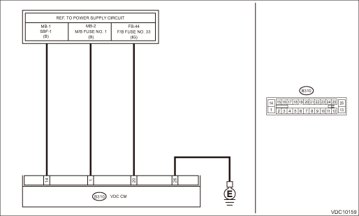
Wiring diagram:
Vehicle dynamics control system Vehicle Dynamics Control System > WIRING DIAGRAM">
| STEP | CHECK | YES | NO |
1.CHECK VDCCM&H/U INPUT VOLTAGE.
1) Turn the ignition switch to OFF.
2) Disconnect the connector from the VDCCM&H/U.
3) Turn the ignition switch to ON.
4) Measure the voltage between VDCCM&H/U connector and chassis ground.
Connector & terminal
(B310) No. 14 (+) — Chassis ground (−):
(B310) No. 20 (+) — Chassis ground (−):
Is the voltage 10 — 15 V?
Diagnostic Procedure with Diagnostic Trouble Code (DTC) > DTC C0052 MOTOR MALFUNCTION">Go to Step 2.
Repair the VDCCM&H/U power supply circuit.
2.CHECK VDCCM&H/U INPUT VOLTAGE.
Calculate the voltage difference measured in step 1.
A: (B310) No. 14 (+) — Chassis ground (−):
B: (B310) No. 20 (+) — Chassis ground (−):
Is the voltage difference between A and B 2 V or more?
Repair the power supply circuit.
Diagnostic Procedure with Diagnostic Trouble Code (DTC) > DTC C0052 MOTOR MALFUNCTION">Go to Step 3.
3.CHECK INSTALLATION OF VDCCM&H/U GROUND.
Is the VDCCM&H/U ground terminal installation bolt (ground bolt fixing onto the side frame upper face) installed correctly?
Diagnostic Procedure with Diagnostic Trouble Code (DTC) > DTC C0052 MOTOR MALFUNCTION">Go to Step 4.
Install the VDCCM&H/U ground terminal installation bolt correctly.
4.CHECK VDCCM&H/U GROUND CIRCUIT (CHECK FOR OPEN CIRCUIT).
1) Turn the ignition switch to OFF.
2) Measure the resistance between VDCCM&H/U connector and chassis ground.
Connector & terminal
(B310) No. 26 — Chassis ground:
Is the resistance less than 10 ??
Diagnostic Procedure with Diagnostic Trouble Code (DTC) > DTC C0052 MOTOR MALFUNCTION">Go to Step 5.
Repair the VDCCM&H/U ground harness.
5.CHECK VDCCM&H/U MOTOR RELAY.
Measure the resistance between VDCCM&H/U terminals.
Connector & terminal
No. 14 — No. 26:
Is the resistance 1 M? or more?
Diagnostic Procedure with Diagnostic Trouble Code (DTC) > DTC C0052 MOTOR MALFUNCTION">Go to Step 6.
Replace the VDCCM&H/U. VDC Control Module and Hydraulic Control Unit (VDCCM&H/U)">
6.CHECK POOR CONTACT OF CONNECTORS.
Turn the ignition switch to OFF.
Is there poor contact of connector between generator, battery and VDCCM&H/U?
Repair the connector.
Diagnostic Procedure with Diagnostic Trouble Code (DTC) > DTC C0052 MOTOR MALFUNCTION">Go to Step 7.
7.CHECK VDCCM&H/U.
1) Connect all connectors.
2) Perform the Clear Memory Mode. Clear Memory Mode">
3) Perform the Inspection Mode. Inspection Mode">
4) Read the DTC. Read Diagnostic Trouble Code (DTC)">
Is the same DTC displayed?
Replace the VDCCM&H/U. VDC Control Module and Hydraulic Control Unit (VDCCM&H/U)">
Diagnostic Procedure with Diagnostic Trouble Code (DTC) > DTC C0052 MOTOR MALFUNCTION">Go to Step 8.
8.CHECK DETECTION OF OTHER DTCS FOR VDC.
Read Diagnostic Trouble Code (DTC)">
Is any other DTC displayed?
Perform the diagnosis according to DTC. List of Diagnostic Trouble Code (DTC)">
Currently, it is normal. There may have been a temporary poor contact in the harness and connector or a temporary noise interference.
 Dtc c0051 valve relay
VEHICLE DYNAMICS CONTROL (VDC) (DIAGNOSTICS) > Diagnostic Procedure with Diagnostic Trouble Code (DTC)DTC C0051 VALVE RELAYDTC detecting condition:Defective valve relayTrouble symptom:• ABS d ...
 Dtc c0054 bls on malfunction
VEHICLE DYNAMICS CONTROL (VDC) (DIAGNOSTICS) > Diagnostic Procedure with Diagnostic Trouble Code (DTC)DTC C0054 BLS ON MALFUNCTIONDTC detecting condition:Defective stop light switchTrouble symptom: ...
Other materials:
Dtc c1222 front left abs sensor signal
VEHICLE DYNAMICS CONTROL (VDC) (DIAGNOSTICS) > Diagnostic Procedure with Diagnostic Trouble Code (DTC)DTC C1222 FRONT LEFT ABS SENSOR SIGNALNOTE:For the diagnostic procedure, refer to “DTC C1242 REAR LEFT ABS SENSOR SIGNAL”. Diagnostic Procedure with Diagnostic Trouble Code (DTC) > ...
Basic diagnostic procedure Procedure
Blind Spot Detection/Rear Cross Traffic Alert (DIAGNOSTICS) > Basic Diagnostic ProcedurePROCEDURESTEPCHECKYESNO1.PERFORM CUSTOMER INTERVIEW.Using the Check List for Interview, ask the customer the condition of how trouble occurs.Did you interview the customer? Basic Diagnostic Procedure > PROC ...
Removal
CONTINUOUSLY VARIABLE TRANSMISSION(TR580) > Drive Pinion Shaft AssemblyREMOVAL1. Remove the transmission assembly from the vehicle. Automatic Transmission Assembly > REMOVAL">2. Remove the air breather hose. Air Breather Hose > REMOVAL">3. Remove the control valve body. C ...
