
Subaru Crosstrek Service Manual: Installation
EXTERIOR BODY PANELS > Front Fender
INSTALLATION
1. Install each part in the reverse order of removal.
CAUTION:
• Install the bumper face - front so that the front end of the under cover (b) comes inside the bumper face - front (a), and the front end of the mud guard (c) comes outside the bumper face - front (a).
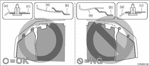
• Before installing the bumper face, match the claws on the bracket - front bumper with the engaging position of flange section on the bumper face side. If the engaging position is not correct, the flange section may be broken or the clearance between fender panel and bumper face may not be uniform.
Tightening torque:
Fender COMPL - front: 7.5 N·m (0.76 kgf-m, 5.5 ft-lb)
Light assembly - head: 7.5 N·m (0.76 kgf-m, 5.5 ft-lb)
NOTE:
When installing the fender COMPL - front, make sure that a uniform clearance is created around it.
• Fender COMPL - front to Hood COMPL - front: Front Hood > ADJUSTMENT">
• Fender COMPL - front to Panel assembly - front door: Front Door > ADJUSTMENT">
2. Adjust the headlight beam and fog light beam.
• Adjust the headlight beam. Headlight Assembly > ADJUSTMENT">
• Adjust the fog light beam. (Model with fog light) Front Fog Light Assembly > ADJUSTMENT">
 Front fender
...
 Removal
EXTERIOR BODY PANELS > Front FenderREMOVAL1. Disconnect the ground cable from battery. NOTE">2. Remove the bumper face - front. Front Bumper > REMOVAL">3. Remove the light asse ...
Other materials:
Dtc b2807 ecm abnormal
EyeSight (DIAGNOSTICS) > Diagnostic Procedure with Diagnostic Trouble Code (DTC)DTC B2807 ECM ABNORMALDetected when cruise indicator illumination request from ECM and ON/OFF information of cruise function do not match.NOTE:• Perform check of the ECM. Basic Diagnostic Procedure > PROCEDU ...
Dtc b1572 imm circuit except antenna circuit
KEYLESS ACCESS WITH PUSH BUTTON START SYSTEM (DIAGNOSTICS) > Diagnostic Procedure with Diagnostic Trouble Code (DTC)DTC B1572 IMM CIRCUIT EXCEPT ANTENNA CIRCUIT1. EXCEPT FOR C0 AND C5 MODELSDTC detecting condition:Communication error between keyless access CM and ECMTrouble symptom:Engine will no ...
Dtc c2023 tire 3 air pressure low (normal mode)
TIRE PRESSURE MONITORING SYSTEM (DIAGNOSTICS) > Diagnostic Procedure with Diagnostic Trouble Code (DTC)DTC C2023 TIRE 3 AIR PRESSURE LOW (NORMAL MODE)NOTE:Refer to DTC C2024 for diagnostic procedure. Diagnostic Procedure with Diagnostic Trouble Code (DTC) > DTC C2024 TIRE 4 AIR PRESSURE LOW ( ...
