Subaru Crosstrek Service Manual: Dtc c1521 motor relay
VEHICLE DYNAMICS CONTROL (VDC) (DIAGNOSTICS) > Diagnostic Procedure with Diagnostic Trouble Code (DTC)
DTC C1521 MOTOR RELAY
DTC detecting condition:
• Defective motor and motor relay
• Defective harness connector
Trouble symptom:
• ABS does not operate.
• VDC does not operate.
• EBD may not operate.
• Hill start assist does not operate.
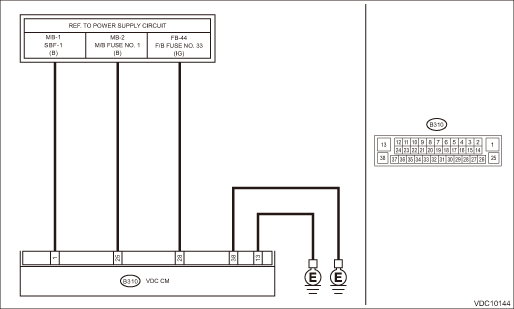
Wiring diagram:
Vehicle dynamics control system Vehicle Dynamics Control System > WIRING DIAGRAM">
| STEP | CHECK | YES | NO |
1.CHECK VDCCM&H/U INPUT VOLTAGE.
1) Turn the ignition switch to OFF.
2) Disconnect the connector from the VDCCM&H/U.
3) Turn the ignition switch to ON.
4) Measure the voltage between VDCCM&H/U connector and chassis ground.
Connector & terminal
(B310) No. 1 (+) — Chassis ground (−):
(B310) No. 28 (+) — Chassis ground (−):
Is the voltage 10 — 15 V?
Diagnostic Procedure with Diagnostic Trouble Code (DTC) > DTC C1521 MOTOR RELAY">Go to Step 2.
Repair the VDCCM&H/U power supply circuit.
2.CHECK VDCCM&H/U INPUT VOLTAGE.
Calculate the voltage difference measured in step 1.
A: (B310) No. 1 (+) — Chassis ground (−):
B: (B310) No. 28 (+) — Chassis ground (−):
Is the voltage difference between A and B 2 V or more?
Repair the power supply circuit.
Diagnostic Procedure with Diagnostic Trouble Code (DTC) > DTC C1521 MOTOR RELAY">Go to Step 3.
3.CHECK INSTALLATION OF VDCCM&H/U GROUND.
Is the VDCCM&H/U ground terminal installation bolt (ground bolt fixing onto the side frame upper face) installed correctly?
Diagnostic Procedure with Diagnostic Trouble Code (DTC) > DTC C1521 MOTOR RELAY">Go to Step 4.
Install the VDCCM&H/U ground terminal installation bolt correctly.
4.CHECK VDCCM&H/U GROUND CIRCUIT (CHECK FOR OPEN CIRCUIT).
1) Turn the ignition switch to OFF.
2) Measure the resistance between VDCCM&H/U connector and chassis ground.
Connector & terminal
(B310) No. 13 — Chassis ground:
(B310) No. 38 — Chassis ground:
Is the resistance less than 10 ??
Diagnostic Procedure with Diagnostic Trouble Code (DTC) > DTC C1521 MOTOR RELAY">Go to Step 5.
Repair the VDCCM&H/U ground harness.
5.CHECK VDCCM&H/U MOTOR RELAY.
Measure the resistance between VDCCM&H/U terminals.
Terminals
No. 1 — No. 13:
Is the resistance 1 M? or more?
Diagnostic Procedure with Diagnostic Trouble Code (DTC) > DTC C1521 MOTOR RELAY">Go to Step 6.
Replace the VDCCM&H/U. VDC Control Module and Hydraulic Control Unit (VDCCM&H/U)">
6.CHECK POOR CONTACT OF CONNECTORS.
Turn the ignition switch to OFF.
Is there poor contact of connector between generator, battery and VDCCM&H/U?
Repair the connector.
Diagnostic Procedure with Diagnostic Trouble Code (DTC) > DTC C1521 MOTOR RELAY">Go to Step 7.
7.CHECK VDCCM&H/U.
1) Connect all connectors.
2) Perform the Clear Memory Mode. Clear Memory Mode">
3) Perform the Inspection Mode. Inspection Mode">
4) Read the DTC. Read Diagnostic Trouble Code (DTC)">
Is the same DTC displayed?
Replace the VDCCM&H/U. VDC Control Module and Hydraulic Control Unit (VDCCM&H/U)">
Diagnostic Procedure with Diagnostic Trouble Code (DTC) > DTC C1521 MOTOR RELAY">Go to Step 8.
8.CHECK DETECTION OF OTHER DTCS FOR VDC.
Read Diagnostic Trouble Code (DTC)">
Is any other DTC displayed?
Perform the diagnosis according to DTC. List of Diagnostic Trouble Code (DTC)">
Currently, it is normal. There may have been a temporary poor contact in the harness and connector or a temporary noise interference.
 Dtc c1512 valve system
VEHICLE DYNAMICS CONTROL (VDC) (DIAGNOSTICS) > Diagnostic Procedure with Diagnostic Trouble Code (DTC)DTC C1512 VALVE SYSTEMNOTE:For the diagnostic procedure, refer to “DTC C1362 NORMAL CLOSI ...
 Dtc u0401 invalid data received from ecm/pcm a
VEHICLE DYNAMICS CONTROL (VDC) (DIAGNOSTICS) > Diagnostic Procedure with Diagnostic Trouble Code (DTC)DTC U0401 INVALID DATA RECEIVED FROM ECM/PCM “A”NOTE:Refer to “LAN SYSTEM&rdq ...
Other materials:
Dtc u0140 lost communication with body control module
CONTINUOUSLY VARIABLE TRANSMISSION (DIAGNOSTICS) > Diagnostic Procedure with Diagnostic Trouble Code (DTC)DTC U0140 LOST COMMUNICATION WITH BODY CONTROL MODULENOTE:Refer to “LAN SYSTEM (DIAGNOSTICS)” for diagnostic procedures. Basic Diagnostic Procedure">1. OUTLINE OF DIAGNOS ...
Adjustment
CONTINUOUSLY VARIABLE TRANSMISSION(TR580) > Transmission CaseADJUSTMENTNOTE:When replacing the transmission case with a new part, perform the following check and adjustment for the selection.• Select the transfer driven gear shim. Transfer Clutch > ADJUSTMENT">• Select the ...
Installation
EXTERIOR BODY PANELS > Front FenderINSTALLATION1. Install each part in the reverse order of removal.CAUTION:• Install the bumper face - front so that the front end of the under cover (b) comes inside the bumper face - front (a), and the front end of the mud guard (c) comes outside the bumpe ...
