Subaru Crosstrek Service Manual: Removal
DRIVE SHAFT SYSTEM > Rear Axle
REMOVAL
1. Disconnect the ground cable from battery. NOTE">
2. Lift up the vehicle, and then remove the rear wheels.
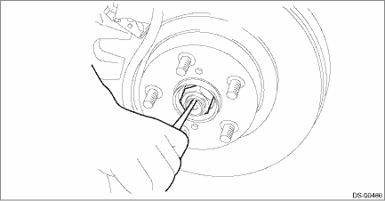
3. Remove the axle nut.
CAUTION:
Do not loosen the axle nut while the rear axle is loaded. Doing so may damage the hub unit bearing.
(1) Lift the crimped section of axle nut.
(2) Remove the axle nut using a socket wrench while depressing the brake pedal.
4. Disconnect the sensor assembly - headlight beam leveler. (Model with auto headlight beam leveler)
CAUTION:
Do not apply impact to the sensor assembly - headlight beam leveler or forcibly move the arm. Doing so may cause sensor damage and malfunction.
(1) Disconnect the connector of the sensor assembly - headlight beam leveler.
(2) Remove the bolts and nuts, and remove the sensor assembly - headlight beam leveler.
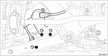
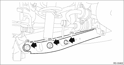
5. Remove the bolts and nuts, and lower the lateral link assembly - rear.
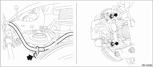
(1) Remove the nut and disconnect the rear stabilizer link. (Model with rear stabilizer)
(2) Remove the bolts at the bottom of rear strut assembly.
(3) Disconnect the rear axle housing from the lateral link assembly - rear.
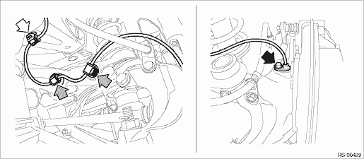
6. Remove the rear ABS wheel speed sensor from the rear axle housing.
(1) Remove the bolts, and remove the ABS wheel speed sensor.
(2) Remove the rear ABS wheel speed sensor harness from the upper arm.
CAUTION:
• Be careful not to damage the sensor.
• Do not apply excessive force to the sensor harness.
• Leave the sensor harness clamp (white arrow) on the vehicle side.
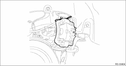
7. Remove the caliper body assembly from the rear axle housing.
(1) Remove the bolts and then remove the brake hose bracket and caliper body assembly.
(2) Prepare wiring harnesses etc. to be discarded, and suspend the caliper body assembly from the strut assembly.
8. Remove the rear disc rotor.
NOTE:
If it is difficult to remove the rear disc rotor, perform the following two methods in order.
(1) Remove the adjusting hole cover (A), insert the flat tip screwdriver, and rotate the adjuster assembly - rear brake until the brake shoe moves far enough to remove the disc rotor.
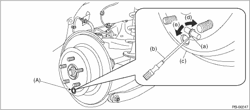
(a) | Adjuster ASSY - rear brake | (c) | Disc rotor | (e) | Shorten the adjuster ASSY - rear brake |
(b) | Flat tip screwdriver | (d) | Extend the adjuster ASSY - rear brake |
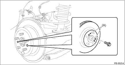
(2) If the disc rotor is not removed after performing above step, screw in an 8 mm (0.31 in) bolt to the threaded part (A) of the disc rotor, and remove the disc rotor.
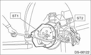
9. Remove the rear drive shaft assembly from the rear hub unit bearing.
NOTE:
If it is hard to remove, use the ST.
Preparation tool:
ST1: AXLE SHAFT PULLER (926470000)
ST2: AXLE SHAFT PULLER PLATE (28099PA110)
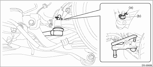
10. Remove the lateral link assembly - front.
(1) Remove the snap pin (a) and nut (b).
(2) Remove the ball joint from the rear axle housing.
CAUTION:
Be careful not to damage the boot of the joint.
Preparation tool:
Tie-rod ball joint puller
11. Remove the rear axle housing.
(1) Remove the bolts for the upper arm, the trailing link, and the lateral link assembly - rear, and then separate the rear axle housing.
CAUTION:
Be careful not to damage the boot of the joint.
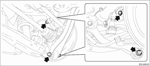
(2) Remove the rear axle housing.
CAUTION:
• Be careful of the weight of rear axle housing.
• Be careful not to damage the spline portion of the drive shaft.
12. Refer to “Rear Hub Unit Bearing” for removal of the rear hub unit bearing. Rear Hub Unit Bearing > REMOVAL">
 Assembly
DRIVE SHAFT SYSTEM > Rear AxleASSEMBLY1. BUSHING - REAR AXLE HOUSINGDo not remove the bushing - rear axle housing from the rear axle housing, because it cannot be replaced. If removed, replace the ...
 Disassembly
DRIVE SHAFT SYSTEM > Rear AxleDISASSEMBLY1. BUSHING - REAR AXLE HOUSINGDo not remove the bushing - rear axle housing from the rear axle housing, because it cannot be replaced. If removed, replace t ...
Other materials:
Dtc p0340 camshaft position sensor "a" circuit bank 1 or single sensor
ENGINE (DIAGNOSTICS)(H4DO) > Diagnostic Procedure with Diagnostic Trouble Code (DTC)DTC P0340 CAMSHAFT POSITION SENSOR "A" CIRCUIT BANK 1 OR SINGLE SENSORDTC DETECTING CONDITION:Immediately at fault recognitionTROUBLE SYMPTOM:• Engine stall• Failure of engine to startCAUTION ...
Initial illumination for system check
When the ignition switch of the Subaru Ascent is turned to the "ON" position,
multiple warning and indicator lights illuminate briefly and then turn off. This
built-in self-check confirms that the systems and indicator bulbs are functioning
correctly.
To perform this system check, a ...
Dtc u0131 lost communication with power steering control module
LAN SYSTEM (DIAGNOSTICS) > Diagnostic Procedure with Diagnostic Trouble Code (DTC)DTC U0131 LOST COMMUNICATION WITH POWER STEERING CONTROL MODULEDTC DETECTING CONDITION:No data is received from power steering CM.TROUBLE SYMPTOM:Cooperation control with power steering CM does not operate properly. ...
