Subaru Crosstrek Service Manual: Removal
CONTINUOUSLY VARIABLE TRANSMISSION(TR580) > Reverse Brake Assembly
REMOVAL
1. Remove the transmission assembly from the vehicle. Automatic Transmission Assembly > REMOVAL">
2. Remove the air breather hose. Air Breather Hose > REMOVAL">
3. Remove the control valve body. Control Valve Body > REMOVAL">
4. Remove the transmission harness. Transmission Harness > REMOVAL">
5. Remove the turbine speed sensor. Turbine Speed Sensor > REMOVAL">
6. Remove the secondary speed sensor. Secondary Speed Sensor > REMOVAL">
7. Remove the primary speed sensor. Primary Speed Sensor > REMOVAL">
8. Remove the inhibitor switch. Inhibitor Switch > REMOVAL">
9. Remove the extension case. Extension Case > REMOVAL">
10. Remove the transfer clutch assembly. Transfer Clutch > REMOVAL">
11. Remove the transfer driven gear assembly. Transfer Driven Gear > REMOVAL">
12. Remove the parking pawl. Parking Pawl > REMOVAL">
13. Remove the reduction driven gear assembly. Reduction Driven Gear > REMOVAL">
14. Remove the oil pan and oil strainer. Oil Pan and Strainer > REMOVAL">
15. Remove the transmission control device. Transmission Control Device > REMOVAL">
16. Remove the transmission case. Transmission Case > REMOVAL">
17. Remove the reduction drive gear. Reduction Drive Gear > REMOVAL">
18. Remove the primary pulley, secondary pulley and variator chain. Primary Pulley and Secondary Pulley > REMOVAL">
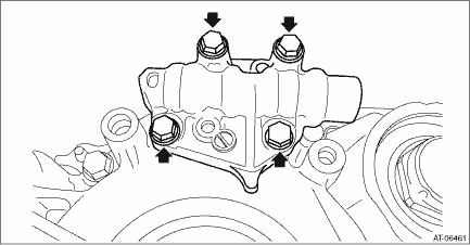
19. Remove the manual valve assembly.
20. Remove the oil guide and lubrication pipe.
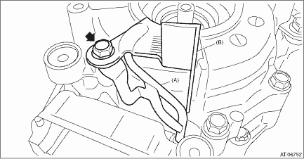
(A) | Lubrication pipe |
(B) | Oil guide |
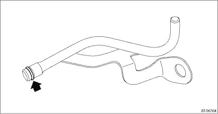
21. Remove the O-ring from lubrication pipe.
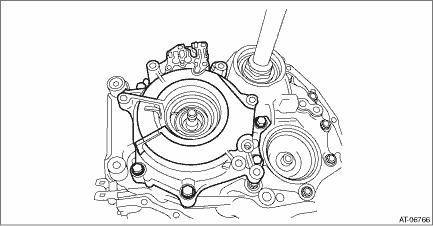
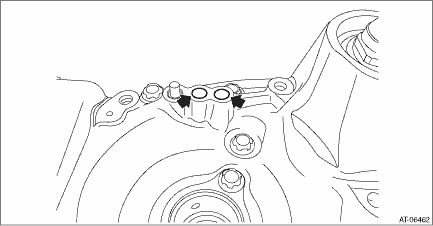
22. Remove the reverse brake assembly.
23. Remove the O-ring.
 Assembly
CONTINUOUSLY VARIABLE TRANSMISSION(TR580) > Reverse Brake AssemblyASSEMBLY1. Install the reverse brake piston.NOTE:Apply CVTF to the sealing area of reverse brake piston.2. Install the return sprin ...
 Disassembly
CONTINUOUSLY VARIABLE TRANSMISSION(TR580) > Reverse Brake AssemblyDISASSEMBLY1. Remove the snap ring.2. Remove the retaining plate, drive plate, driven plate and dish plate.3. Compress the return s ...
Other materials:
Dtc b2903 vdc data error
AUTO HEADLIGHT BEAM LEVELER SYSTEM (DIAGNOSTICS) > Diagnostic Procedure with Diagnostic Trouble Code (DTC)DTC B2903 VDC DATA ERRORDTC DETECTING CONDITION:Detected when data (vehicle speed signal) from VDC CM is abnormal.TROUBLE SYMPTOM:The auto headlight beam leveler does not operate.NOTE:Perform ...
Remote keyless entry system
CAUTION
Do not expose the remote transmitter
to severe shocks, such as
those experienced as a result of
dropping or throwing.
Do not take the remote transmitter
apart except when replacing
the battery
Do not get the remote transmitter
wet. If it gets wet, wipe it dry with
a clo ...
Removal
MANUAL TRANSMISSION AND DIFFERENTIAL(5MT) > Front Differential AssemblyREMOVAL1. Remove the manual transmission assembly from the vehicle. Manual Transmission Assembly > REMOVAL">2. Remove the transfer case together with the extension case assembly. Transfer Case and Extension Case A ...
