Subaru Crosstrek Service Manual: Fuel Procedure
FUEL INJECTION (FUEL SYSTEMS)(H4DO) > Fuel
PROCEDURE
1. RELEASING OF FUEL PRESSURE
WARNING:
Place “NO OPEN FLAMES” signs near the working area.
CAUTION:
Be careful not to spill fuel.
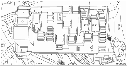
1. Remove the fuse of fuel pump from main fuse box.
2. Start the engine and run it until it stalls.
3. After the engine stalls, crank it for five more seconds.
4. Turn the ignition switch to OFF.
5. Install the fuse of fuel pump to the main fuse box.
2. DRAINING FUEL (WITH SUBARU SELECT MONITOR)
WARNING:
Place “NO OPEN FLAMES” signs near the working area.
CAUTION:
Be careful not to spill fuel.
NOTE:
• If the fuel pump cannot be driven, refer to the procedures for draining from the fuel filler hose. Fuel > PROCEDURE">
• Be careful not to let the battery run-out.
• Be aware that the fuel may remain in the fuel tank after draining the fuel.
1. Release the fuel pressure. Fuel > PROCEDURE">
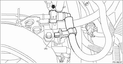
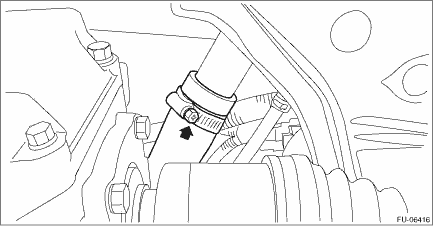
2. Disconnect the quick connector on the fuel delivery tube from the fuel pipe assembly, and remove the clip (A) securing the fuel delivery tube to the fuel pipe assembly.
CAUTION:
• Be careful not to spill fuel.
• Catch the fuel from the tubes using a container or cloth.
NOTE:
Disconnect the quick connector as shown in the figure.
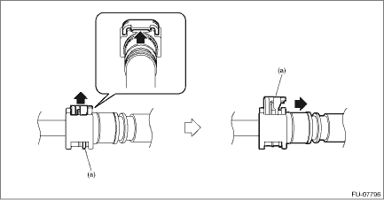
(a) | Slider |
3. Connect ST to the fuel delivery tube.
| ST 18471AA000 | FUEL PIPE ADAPTER |
4. Connect the gasoline proof hose to ST and put the end of the hose in the container.
5. Drive the fuel pump and drain the fuel using Subaru Select Monitor.
CAUTION:
Be careful not to spill fuel.
NOTE:
For detailed operation procedures of Subaru Select Monitor 4, refer to “Application help”.
6. Install the related parts in the reverse order after draining the fuel.
CAUTION:
• Be careful not to spill fuel.
• Catch the fuel from the tubes using a container or cloth.
• Check that there is no damage or dust on the quick connector. If necessary, clean the seal surface of the pipe.
• When connecting the quick connector, make sure to insert it all the way in before locking the slider.
• When it is difficult to lock the slider, check that the connector is fully inserted.
• After locking the slider, check again that the quick connector is securely connected.
NOTE:
• Disconnect the quick connector on the fuel delivery tube as shown in the figure.
(a) | Slider |
• Connect the quick connector on the fuel delivery tube as shown in the figure.
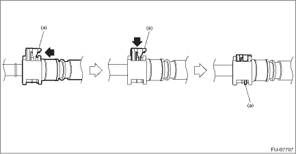
(a) | Slider |
3. DRAINING FUEL (THROUGH THE FUEL FILLER HOSE)
WARNING:
Place “NO OPEN FLAMES” signs near the working area.
CAUTION:
• Be careful not to spill fuel.
• Fuel may remain in the fuel filler pipe. Drain the fuel from the fuel filler pipe through the fill opening using the gasoline proof pump and the gasoline proof hose (o10 or less) before the operation.
NOTE:
Be aware that the fuel may remain in the fuel tank after draining the fuel.
1. Lift up the vehicle.
2. Remove the rear exhaust pipe and muffler. Rear Exhaust Pipe > REMOVAL"> Muffler > REMOVAL">
3. Open the fuel filler lid and remove the fuel filler cap.
4. Drain the fuel from the fuel filler pipe through the filler opening using the gasoline proof pump and the gasoline proof hose (o10 or less).
5. Disconnect the fuel filler hose from the fuel filler pipe assembly.
CAUTION:
• Be careful not to spill fuel.
• Catch the fuel from hoses using a container or cloth.
6. Set the container under the vehicle and insert the gasoline proof hose (o10 or less) into the fuel filler hose to drain the fuel.
CAUTION:
Be careful not to spill fuel.
7. Install the related parts in the reverse order after draining the fuel.
NOTE:
Correctly insert the fuel filler hose to the spool, and then install the clamp as shown.
Tightening torque:
2.5 N·m (0.3 kgf-m, 1.8 ft-lb)
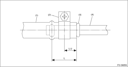
(1) | Fuel filler hose | (3) | Spool | (4) | Fuel filler pipe |
(2) | Clamp |
 Installation
FUEL INJECTION (FUEL SYSTEMS)(H4DO) > Tumble Generator Valve AssemblyINSTALLATIONInstall in the reverse order of removal.NOTE:Use a new gasket.Tightening torque:25 N·m (2.5 kgf-m, 18.4 ft-lb ...
 Fuel system trouble in general Inspection
FUEL INJECTION (FUEL SYSTEMS)(H4DO) > Fuel System Trouble in GeneralINSPECTIONTroublePossible causeCorrective actionInsufficient fuel supply to fuel injectora. Fuel pump does not operate. Defec ...
Other materials:
How to change the source
The Pandora operation screen can be
reached by the following methods:
Connecting a Pandora device. Refer to
"Connecting a Bluetooth device" F5-68 or
"Connecting and disconnecting a USB
memory/portable device" F5-17.
Select the "Pandora" key on the source
select screen. Refer to "Selec ...
Adjustment
CONTINUOUSLY VARIABLE TRANSMISSION(TR580) > Primary Pulley and Secondary PulleyADJUSTMENT1. PROCEDURE IN REPLACEMENT OF PRIMARY AND SECONDARY PULLEY, OR IN REPLACEMENT OF PRIMARY PULLEY, SECONDARY PULLEY AND VARIATOR CHAIN1. Measure depth “Lp” from the ST upper face to the primary pul ...
Dtc p2750 intermediate shaft speed sensor "c" circuit range/performance
CONTINUOUSLY VARIABLE TRANSMISSION (DIAGNOSTICS) > Diagnostic Procedure with Diagnostic Trouble Code (DTC)DTC P2750 INTERMEDIATE SHAFT SPEED SENSOR "C" CIRCUIT RANGE/PERFORMANCEDTC detecting condition:Immediately at fault recognitionTrouble symptom:• Shifting shock is felt.• ...
