Subaru Crosstrek Service Manual: Adjustment
CONTINUOUSLY VARIABLE TRANSMISSION(TR580) > Primary Pulley and Secondary Pulley
ADJUSTMENT
1. PROCEDURE IN REPLACEMENT OF PRIMARY AND SECONDARY PULLEY, OR IN REPLACEMENT OF PRIMARY PULLEY, SECONDARY PULLEY AND VARIATOR CHAIN
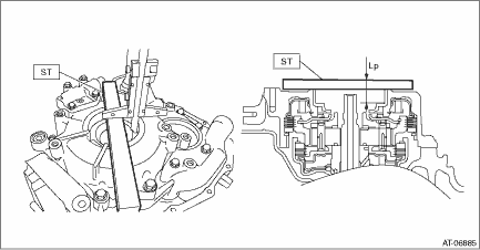
1. Measure depth “Lp” from the ST upper face to the primary pulley bearing catch surface at several points and calculate the average.
| ST 499575400 | GAUGE |
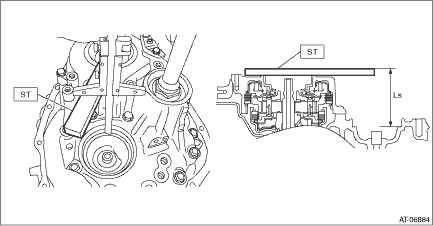
2. Measure the depth “Ls” from the ST upper face to the secondary pulley bearing catch surface at several points and calculate the average.
| ST 499575400 | GAUGE |
3. Calculate the following formula.
Calculation formula:
T (mm) = B − A + Lp − Ls − 28.602
[T (in) = B − A + Lp − Ls − 1.126]
T: Pulley alignment
A: Specified primary pulley dimension
B: Specified secondary pulley dimension
Lp: Depth from the ST upper face to the primary pulley bearing catch surface
Ls: Depth from the ST upper face to the secondary pulley bearing catch surface
28.602 mm (1.126 in): Constant
Pulley alignment T mm (in) | Thickness of shim mm (in) |
−0.05 — 0.049 (−0.002 — 0.002) | No shims |
0.050 — 0.149 (0.002 — 0.006) | 0.1 (0.004) |
0.150 — 0.249 (0.006 — 0.010) | 0.2 (0.008) |
0.250 — 0.349 (0.010 — 0.014) | 0.3 (0.012) |
0.350 — 0.449 (0.014 — 0.018) | 0.4 (0.016) |
0.450 — 0.549 (0.018 — 0.022) | 0.5 (0.020) |
0.550 — 0.649 (0.022 — 0.026) | 0.6 (0.024) |
0.650 — 0.749 (0.026 — 0.029) | 0.7 (0.028) |
0.750 — 0.849 (0.029 — 0.033) | 0.8 (0.031) |
0.850 — 0.949 (0.033 — 0.037) | 0.9 (0.035) |
0.950 — 1.049 (0.037 — 0.041) | 1.0 (0.039) |
1.050 — 1.149 (0.041 — 0.045) | 1.1 (0.043) |
4. Select one to two shims so that the total thickness meets the value obtained from step 3).
Part No. | Shim thickness mm (in) |
32451AA050 | 0.1 (0.004) |
32451AA060 | 0.2 (0.008) |
32451AA070 | 0.3 (0.012) |
32451AA080 | 0.4 (0.016) |
32451AA090 | 0.5 (0.020) |
32451AA100 | 0.6 (0.024) |
2. PROCEDURE WHEN REPLACING ONLY DRIVE PINION RETAINER OR REVERSE BRAKE HOUSING
1. Clean the mating surface of current drive pinion retainer and converter case.
2. Measure and record the shim thickness that is attached on the current reverse brake housing.
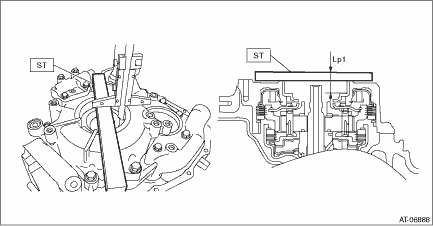
3. Using the current drive pinion retainer, measure depth “Lp1” from the ST upper face to the primary pulley bearing catch surface at several points and calculate the average.
| ST 499575400 | GAUGE |
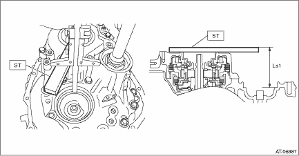
4. Using the current drive pinion retainer or current reverse brake housing, measure the depth “Ls1” from the ST upper face to the secondary pulley bearing catch surface at several points and calculate the average.
| ST 499575400 | GAUGE |
5. Calculate the “LD1” using the following formula and record it.
Calculation formula:
LD1 mm (in) = Ls1 − Lp1
LD1: Height from the primary pulley bearing catch surface to the secondary pulley bearing catch surface
Lp1: Depth from the ST upper face to the primary pulley bearing catch surface
Ls1: Depth from the ST upper face to the secondary pulley bearing catch surface
6. Using the new drive pinion retainer or new reverse brake housing, measure the depth “Lp2” from the ST upper face to the primary pulley bearing catch surface at several points and calculate the average.
| ST 499575400 | GAUGE |
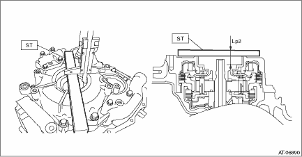
7. Using the new drive pinion retainer or new reverse brake housing, measure the depth “Ls2” from the ST upper face to the secondary pulley bearing catch surface at several points and calculate the average.
| ST 499575400 | GAUGE |
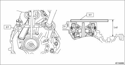
8. Calculate the “LD2” using the following formula and record it.
Calculation formula:
LD2 mm (in) = Ls2 − Lp2
LD2: Height from the primary pulley bearing catch surface to the secondary pulley bearing catch surface
Lp2: Depth from the ST upper face to the primary pulley bearing catch surface
Ls2: Depth from the ST upper face to the secondary pulley bearing catch surface
9. Calculate the recorded values of “LD1” and “LD2” to obtain the positive number to select the shims.
Calculation formula: T1 mm (in) = LD1 − LD2 or T2 mm (in) = LD2 − LD1
T1, T2: Difference between new drive pinion retainer or new reverse brake housing and current drive pinion retainer or current reverse brake housing
LD1: Calculated value of current drive pinion retainer or current reverse brake housing
LD2: Calculated value of new drive pinion retainer or new reverse brake housing
Difference of the case (T1) mm (in) | Shim selection procedure |
0 — 0.050 (0 — 0.00197) | Select a new shim of the same thickness with the shim that is used on the primary pulley side of the current reverse brake housing. |
0.051 — 0.150 (0.00201 — 0.00591) | Select a shim which is 0.1 mm (0.004 in) thicker than the shim that is used on the primary pulley side of the current reverse brake housing. |
0.151 — 0.250 (0.00594 — 0.00984) | Select a shim which is 0.2 mm (0.008 in) thicker than the shim that is used on the primary pulley side of the current reverse brake housing. |
0.251 — 0.350 (0.00988 — 0.01378) | Select a shim which is 0.3 mm (0.012 in) thicker than the shim that is used on the primary pulley side of the current reverse brake housing. |
0.351 — 0.450 (0.01382 — 0.01772) | Select a shim which is 0.4 mm (0.016 in) thicker than the shim that is used on the primary pulley side of the current reverse brake housing. |
0.451 — 0.550 (0.01776 — 0.02165) | Select a shim which is 0.5 mm (0.020 in) thicker than the shim that is used on the primary pulley side of the current reverse brake housing. |
0.551 — 0.600 (0.02169 — 0.02362) | Select a shim which is 0.6 mm (0.024 in) thicker than the shim that is used on the primary pulley side of the current reverse brake housing. |
Difference of the case (T2) mm (in) | Shim selection procedure |
0 — 0.050 (0 — 0.00197) | Select a new shim of the same thickness with the shim that is used on the primary pulley side of the current reverse brake housing. |
0.051 — 0.150 (0.00201 — 0.00591) | Select a shim which is 0.1 mm (0.004 in) thinner than the shim that is used on the primary pulley side of the current reverse brake housing. |
0.151 — 0.250 (0.00594 — 0.00984) | Select a shim which is 0.2 mm (0.008 in) thinner than the shim that is used on the primary pulley side of the current reverse brake housing. |
0.251 — 0.350 (0.00988 — 0.01378) | Select a shim which is 0.3 mm (0.012 in) thinner than the shim that is used on the primary pulley side of the current reverse brake housing. |
0.351 — 0.450 (0.01382 — 0.01772) | Select a shim which is 0.4 mm (0.016 in) thinner than the shim that is used on the primary pulley side of the current reverse brake housing. |
0.451 — 0.550 (0.01776 — 0.02165) | Select a shim which is 0.5 mm (0.020 in) thinner than the shim that is used on the primary pulley side of the current reverse brake housing. |
0.551 — 0.600 (0.02169 — 0.02362) | Select a shim which is 0.6 mm (0.024 in) thinner than the shim that is used on the primary pulley side of the current reverse brake housing. |
Part No. | Shim thickness mm (in) |
32451AA050 | 0.1 (0.004) |
32451AA060 | 0.2 (0.008) |
32451AA070 | 0.3 (0.012) |
32451AA080 | 0.4 (0.016) |
32451AA090 | 0.5 (0.020) |
32451AA100 | 0.6 (0.024) |
 Removal
CONTINUOUSLY VARIABLE TRANSMISSION(TR580) > Primary Pulley and Secondary PulleyREMOVALNOTE:Always replace primary pulley and secondary pulley as an assembly because they are non-disassembled parts. ...
Other materials:
Removal
SECURITY AND LOCKS > Keyless Access CMREMOVALCAUTION:Before handling the airbag system components, refer to “CAUTION” of “General Description” in “AIRBAG SYSTEM”. General Description > CAUTION">1. Disconnect the ground cable from battery and wait fo ...
Intake manifold vacuum Inspection
MECHANICAL(H4DO) > Intake Manifold VacuumINSPECTION1. Turn the ignition switch to OFF.2. Warm up the engine.3. Install the vacuum gauge.(1) Remove the brake booster vacuum hose from the intake manifold.(2) Connect the vacuum gauge to the intake manifold.4. Keep the engine at idle speed and read t ...
List of diagnostic trouble code (dtc) List
VEHICLE DYNAMICS CONTROL (VDC) (DIAGNOSTICS) > List of Diagnostic Trouble Code (DTC)LIST• Models without EyeSightDTCItemContent of diagnosisReferenceC1211FRONT RIGHT ABS SENSOR CIRCUITOpen/high input of front ABS wheel speed sensor RH Diagnostic Procedure with Diagnostic Trouble Code (DTC) ...

