Subaru Crosstrek Service Manual: Removal
CLUTCH SYSTEM > Clutch Pedal
REMOVAL
CAUTION:
Before handling the airbag system components, refer to “CAUTION” of “General Description” in “AIRBAG SYSTEM”. General Description > CAUTION">
1. Turn the ignition switch to OFF.
2. Disconnect the ground cable from battery and wait for at least 60 seconds before starting work. NOTE">
3. Remove the steering column. Steering Column > REMOVAL">
4. Disconnect the connector from the stop light switch and clutch switch.
5. Remove the snap pins from clevis pins which secure the lever to the push rod and operating rod.
6. Pull out the clevis pins which secures the lever to the push rod and operating rod.
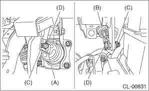
(A) | Operating rod |
(B) | Push rod |
(C) | Snap pin |
(D) | Clevis pin |
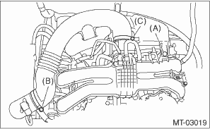
7. Remove the clip (A) from the air intake boot.
8. Loosen the clamp (B) connecting the air intake boot and air cleaner case (rear).
9. Loosen the clamp (C) which connects the air intake boot and throttle body.
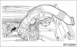
10. Remove the air intake boot from the throttle body, and move it to the left side wheel apron.
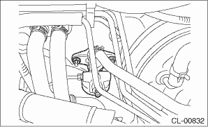
11. Remove the nut which secures the clutch master cylinder.
NOTE:
• Remove the master cylinder from the stud bolt.
• Hold the clutch pipe with a wire or a string to avoid the pipe from bending.
12. Remove the bolts and nuts which secure the brake pedal and clutch pedal, and remove the pedal assembly.
 Adjustment
CLUTCH SYSTEM > Clutch PedalADJUSTMENT1. Turn the lock nut until the full stroke of clutch pedal becomes within the specification.CAUTION:When adjusting the full stroke of clutch pedal, do not turn ...
 Assembly
CLUTCH SYSTEM > Clutch PedalASSEMBLY1. Install the stopper and pedal pad to the clutch pedal.2. Install the clutch switch to the pedal bracket.3. Clean the pedal bushing holes of the clutch pedal a ...
Other materials:
Installation
CONTINUOUSLY VARIABLE TRANSMISSION(TR580) > CVTF Cooler (With Warmer Function)INSTALLATION1. Install the CVTF cooler (with warmer feature) to the transmission.Tightening torque:23 N·m (2.3 kgf-m, 17.0 ft-lb)2. Install the engine coolant inlet hose.NOTE:With the triangle mark on the engine ...
Component
EXHAUST(H4DO) > General DescriptionCOMPONENT1. FRONT EXHAUST PIPE AND CENTER EXHAUST PIPE(1)Front exhaust pipe(12)Front exhaust pipe lower coverTightening torque: N·m (kgf-m, ft-lb)(2)Front catalytic converter(13)Front catalytic converter lower cover LHT1:13 (1.3, 9.6)(3)Center exhaust pip ...
Starting engine
1. Apply the parking brake.
2. Shift the select lever into the "P"
position.
3. Depress the brake pedal.
4. Hold the access key with the buttons
facing you, and touch the push-button
ignition switch with it.
When the communication between the
access key and the vehicle is completed ...
