Subaru Crosstrek Service Manual: Removal
BRAKE > Rear Disc Rotor
REMOVAL
1. Lift up the vehicle, and then remove the rear wheels.
2. Release the lever assembly - hand brake.
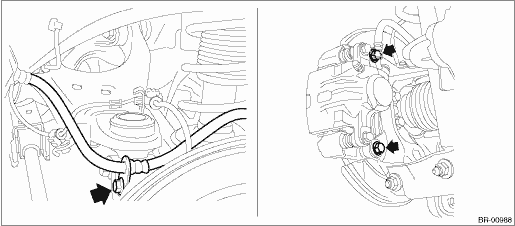
3. Remove the caliper body assembly from the housing assembly - rear axle.
(1) Remove the bolt from the brake hose bracket.
(2) Remove the mounting bolt, and remove the caliper body assembly.
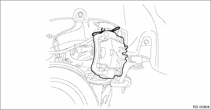
(3) Prepare wiring harnesses etc. to be discarded, and suspend the caliper body assembly from the shock absorber assembly - rear with the harnesses.
4. Remove the rear disc rotor.
NOTE:
If it is difficult to remove the disc rotor, perform the following two methods in order.
(1) Remove the adjusting hole cover (A), and loosen the adjuster assembly - rear brake by inserting a flat tip screwdriver.
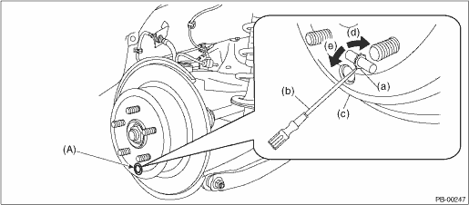
(a) | Adjuster ASSY - rear brake | (c) | Disc rotor | (e) | Shorten the adjuster ASSY - rear brake |
(b) | Flat tip screwdriver | (d) | Extend the adjuster ASSY - rear brake |
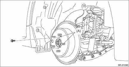
(2) When the disc rotor is difficult to be removed from the hub unit COMPL - rear axle, screw in 8 mm (0.31 in) bolt to the threaded part of the disc rotor (A), and remove the disc rotor.
 Inspection
BRAKE > Rear Disc RotorINSPECTION1. DISC ROTOR RUNOUT CHECK1. Check the hub unit COMPL - rear axle for free play and runout before the inspection of disc rotor runout limit. Rear Hub Unit Bearing ...
 Installation
BRAKE > Rear Disc RotorINSTALLATIONNOTE:Before installation, remove mud and foreign matter from the caliper body assembly.1. Before installation, check the rear disc rotor. Rear Disc Rotor > IN ...
Other materials:
Using a flat-bed truck
Transporting your Subaru Ascent on a flat-bed truck is considered the safest
and most reliable method, as it prevents unnecessary stress on the drivetrain and
suspension components. To ensure maximum safety and avoid potential damage, always
follow the correct loading and securing procedur ...
Removal
CONTINUOUSLY VARIABLE TRANSMISSION(TR580) > Turbine Speed SensorREMOVALCAUTION:Be sure to prevent water or oil from contacting the connector terminal of turbine speed sensor. If adhesion occurs, replace with a new part.1. Lift up the vehicle.2. Remove the harness connector from turbine speed sens ...
Removal
EMISSION CONTROL (AUX. EMISSION CONTROL DEVICES)(H4DO) > EGR PipeREMOVAL1. Disconnect the ground cable from battery.2. Remove the clip (A), and loosen the clamps (B) and (C) securing the air intake boot.3. Remove the air intake boot from the air cleaner case (rear) and throttle body, and move the ...
