Subaru Crosstrek Service Manual: Inspection
BRAKE > Rear Disc Rotor
INSPECTION
1. DISC ROTOR RUNOUT CHECK
1. Check the hub unit COMPL - rear axle for free play and runout before the inspection of disc rotor runout limit. Rear Hub Unit Bearing > INSPECTION">
2. Check the disc rotor runout.
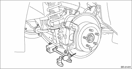
(1) Remove the caliper body assembly. Rear Disc Brake Assembly > REMOVAL">
(2) Secure the disc rotor by tightening the five wheel nuts.
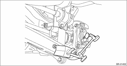
(3) Set a dial gauge 10 mm (0.39 in) inward from the disc rotor outer circumference, and check the outer disc rotor runout while rotating the disc rotor.
Disc rotor runout limit:
0.05 mm (0.0020 in)
(4) Set a dial gauge 10 mm (0.39 in) inward from the disc rotor outer circumference, and check the inner disc rotor runout while rotating the disc rotor.
Disc rotor runout limit:
0.05 mm (0.0020 in)
3. If the disc rotor runout exceeds service limit, resurface the disc rotor.
4. Check the disc rotor thickness after resurfacing. Rear Disc Rotor > INSPECTION">
2. DISC ROTOR THICKNESS CHECK
1. Set a micrometer 10 mm (0.39 in) inward from the disc rotor outer perimeter, and then measure the disc rotor thickness (A).
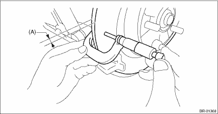
Type of disc rotor | Standard | Wear limit | Disc rotor outer diameter | |
Disc rotor thickness (A) | Solid disc | 10 mm (0.39 in) | 8.5 mm (0.33 in) | 274 mm (10.79 in) |
2. If the wear limit is exceeded in the inspection, replace the disc rotor.
 Rear disc rotor
...
 Removal
BRAKE > Rear Disc RotorREMOVAL1. Lift up the vehicle, and then remove the rear wheels.2. Release the lever assembly - hand brake.3. Remove the caliper body assembly from the housing assembly - rear ...
Other materials:
Dtc b1803 short in driver s airbag (to +b)
AIRBAG SYSTEM (DIAGNOSTICS) > Diagnostic Chart with Trouble CodeDTC B1803 SHORT IN DRIVER’S AIRBAG (TO +B)Diagnosis start condition:Ignition voltage is 10 V to 16 V.DTC detecting condition:• Airbag main harness circuit is shorted to power supply.• Airbag module harness (driver&r ...
Installation
MANUAL TRANSMISSION AND DIFFERENTIAL(5MT) > Reverse Idler GearINSTALLATION1. Install the reverse shifter lever, adjusting washer, reverse idler gear, reverse idler gear shaft and washer, and secure them with the straight pin.NOTE:• Be sure to install the reverse idler gear shaft from rear s ...
Electrical specification
INSTRUMENTATION/DRIVER INFO > Multi-function Display (MFD) SystemELECTRICAL SPECIFICATION1. MULTI FUNCTION DISPLAY• Standard typeTerminal No.ItemMeasuring conditionStandard1 (+B) ←> Chassis groundVoltageAlways10 — 14 V2 (GND) ←> Chassis groundResistanceAlwaysLess than 1 ?3 ...
