Subaru Crosstrek Service Manual: Pressure switch (triple pressure switch) Inspection
HVAC SYSTEM (HEATER, VENTILATOR AND A/C) > Pressure Switch (Triple Pressure Switch)
INSPECTION
1. Connect the manifold gauge to the service valve on the high-pressure side.
2. Disconnect the connector.
3. Start the air conditioner, and check the operating pressure of switch by turning the compressor assembly (magnet clutch) to ON/OFF. Operation of each switch is as follows.
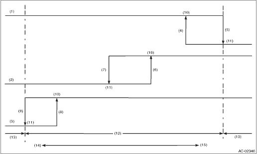
(1) | High pressure switch | (6) | 1,770±100 kPa (18.05±1.02 kg/cm2, 256.65±14.5 psi) | (11) | OFF |
(2) | Middle pressure switch | (7) | 1,470±120 kPa (14.99±1.22 kg/cm2, 213.15±17.4 psi) | (12) | Operative range of compressor ASSY |
(3) | Low pressure switch | (8) | 225±30 kPa (2.29±0.31 kg/cm2, 32.6±4.3 psi) | (13) | Inoperative range of compressor ASSY |
(4) | 2,350±200 kPa (24.00±2.04 kg/cm2, 340.7±29.0 psi) | (9) | 196±25 kPa (2.00±0.25 kg/cm2, 28.4±3.6 psi) | (14) | Low pressure |
(5) | 2,940±200 kPa (29.98±2.04 kg/cm2, 426.3±29.0 psi) | (10) | ON | (15) | High pressure |
NOTE:
• High pressure switch turns the compressor assembly (magnet clutch) to OFF when the refrigerant pressure becomes extremely high to prevent the evaporator, air conditioner piping and expansion valve from getting damaged or frozen, etc.
• The middle pressure switch is used to effectively control the radiator fan output by judging high load/low load in normal pressure range.
• The low pressure switch detects a refrigerant shortage and deactivates the compressor assembly (magnet clutch) if the refrigerant pressure is abnormally low. (Because any further compressor assembly operation in such a state may lead to compressor seizure)
 Diagnostics with phenomenon Inspection
HVAC SYSTEM (HEATER, VENTILATOR AND A/C) > Diagnostics with PhenomenonINSPECTIONRefer to “Diagnostics with Phenomenon” for “HVAC SYSTEM (AUTO A/C) (DIAGNOSTICS)” section. D ...
 Refrigerant charging procedure Procedure
HVAC SYSTEM (HEATER, VENTILATOR AND A/C) > Refrigerant Charging ProcedurePROCEDURECAUTION:• While working, be sure to wear protective goggles and protective gloves.• Air in the cycle ca ...
Other materials:
Dtc c0052 motor malfunction
VEHICLE DYNAMICS CONTROL (VDC) (DIAGNOSTICS) > Diagnostic Procedure with Diagnostic Trouble Code (DTC)DTC C0052 MOTOR MALFUNCTIONDTC detecting condition:• Defective motor and motor relay• Defective harness connectorTrouble symptom:• ABS does not operate.• VDC does not oper ...
Inspection
CONTROL SYSTEMS > AT Shift Lock Control SystemINSPECTION1. SHIFT LOCK OPERATION• Model without push button ignition switchSTEPCHECKYESNO1.CHECK COMMUNICATION OF SUBARU SELECT MONITOR.1) Turn the ignition switch to ON.2) Using the Subaru Select Monitor, check whether communication to all sys ...
Interior light system Wiring diagram
WIRING SYSTEM > Interior Light SystemWIRING DIAGRAM1. WITHOUT EyeSight2. WITH EyeSight ...
