Subaru Crosstrek Service Manual: Precautions in trouble diagnosis and repair of electric parts
WIRING SYSTEM > Working Precautions
PRECAUTIONS IN TROUBLE DIAGNOSIS AND REPAIR OF ELECTRIC PARTS
1. The battery cable must be disconnected from the battery’s (−) terminal, and the ignition switch must be set to the OFF position, unless otherwise required by the diagnostics.
2. Securely fasten the wiring harness with clamps and clips so that the harness does not interfere with the body end parts, edges, bolts or screws.
3. When installing parts, be careful not to catch them on the wiring harness.
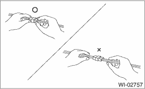
4. When disconnecting a connector, do not pull the wires, but pull while holding the connector body.
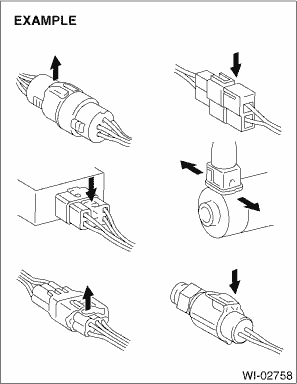
5. Some connectors are provided with a lock. One type of such a connector is disconnected by pushing the lock, and the other, by moving the lock up. In either type the lock shape must be identified before attempting to disconnect the connector.
To connect, insert the connector until it snaps and confirm that it is connected securely.
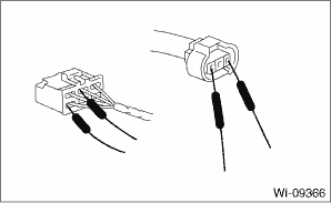
6. When checking continuity between connector terminals, or measuring voltage across the terminal and ground, always touch tester probe(s) to terminals from the wiring connection side. If the probe is too thick to gain access to the terminal, use “mini” test leads.
To check water-proof connectors (which are not measurable from the wiring side), touch test probes on the terminal side and be careful not to bend or damage the terminals.
7. When measuring the voltage or resistance of individual sensor or all electrical control modules, use a tapered pin with a diameter of 0.6 mm (0.024 in) or less and touch it to the tip of terminal. Never insert the tapered pin into the terminal at this time. Doing so may cause internal deformation and a malfunction can occur.
8. Sensors, relays, electrical unit, etc., are sensitive to strong impacts.
Handle them with care so that they are not dropped or mishandled.
 Precautions when working with the parts mounted on the vehicle
WIRING SYSTEM > Working PrecautionsPRECAUTIONS WHEN WORKING WITH THE PARTS MOUNTED ON THE VEHICLE1. When working under a vehicle which is jacked-up, always be sure to use rigid rack.2. The parking ...
 Air conditioning system Wiring diagram
WIRING SYSTEM > Air Conditioning SystemWIRING DIAGRAM1. MANUAL A/C MODEL2. AUTO A/C MODEL ...
Other materials:
Dtc p0300 random/multiple cylinder misfire detected
ENGINE (DIAGNOSTICS)(H4DO) > Diagnostic Procedure with Diagnostic Trouble Code (DTC)DTC P0300 RANDOM/MULTIPLE CYLINDER MISFIRE DETECTEDDTC DETECTING CONDITION:• Detected when two consecutive driving cycles with fault occur.• Immediately at fault recognition (A misfire which could dama ...
Bluetooth settings
Touch the tab to set Bluetooth.
Item
Function
BT Devices
Connection
Select to pair/connect the Bluetooth
devices.
In-Car-Device
setting
Select to enter the Bluetooth
device name or PIN-code.
For details, refer to "Bluetoothsettings"
F5-65. ...
Entering letters and numbers/list screen operation
Entering letters and numbers
When entering the Bluetooth device name
or PIN-code, or the phone number, letters
and numbers can be entered via the
screen.
Enter letters (example: In-Car-Device
setting)
Enter the desired characters (alphabet
key mode).
Switch to the screen for charac ...
