Subaru Crosstrek Service Manual: Location
LIGHTING SYSTEM > Relay and Fuse
LOCATION
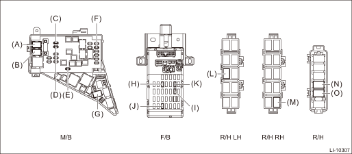
Main fuse box | Headlight relay (HI) | (A) |
Headlight relay (LO) | (B) | |
Fuse 15 A (daytime running light relay) | (C) | |
Fuse 30 A (combination light LH/RH) | (D) | |
Fuse 20 A (spot map light, room light, ignition switch illumination (immobilizer antenna)) | (E) | |
Fuse 15 A (tail and illumination relay, daytime running light relay) | (F) | |
Daytime running light relay | (G) | |
Relay & fuse box | Fuse 10 A (stop light and brake switch, brake relay) | (H) |
Fuse 10A (inhibitor switch, back-up light switch, auto headlight beam leveler CU) | (I) | |
Fuse 15A (front fog light relay*2, front fog light relay LH/RH*1) | (J) | |
Fuse 7.5 A (turn signal & hazard unit) | (K) | |
Relay holder LH (passenger room) | Tail & illumination relay | (L) |
Relay holder RH (passenger room) | Front fog light relay*1 | (M) |
Relay holder (engine compartment) | Front fog light relay RH*2 | (N) |
Front fog light relay LH*2 | (O) |
*1: Model without SRF
*2: Model with SRF
NOTE:
For other related fuses, refer to the wiring diagram. Power Supply Circuit">
 Inspection
LIGHTING SYSTEM > Relay and FuseINSPECTION1. CHECK FUSE1. Remove the fuse and inspect visually.2. If the fuse is blown out, replace the fuse.NOTE:If the fuse is blown again, check the system wiring ...
 Room light
...
Other materials:
Spark plugs
Replacing spark plugs in your Subaru Ascent can be technically challenging due
to limited access and engine layout. For this reason, it is recommended to have
this service performed by a qualified SUBARU dealer.
Spark plugs should be replaced at the intervals specified in the "Warranty and ...
Removal
GLASS/WINDOWS/MIRRORS > Rear Door GlassREMOVAL1. Disconnect the ground cable from battery. NOTE">2. Remove the trim panel - rear door. Door Trim > REMOVAL">3. Remove the sealing cover - rear door. Rear Sealing Cover > REMOVAL">4. Attach the battery ground cable an ...
Wheel bearing Inspection
PERIODIC MAINTENANCE SERVICES > Wheel BearingINSPECTION1. FRONT WHEEL BEARINGNOTE:Inspect the condition of front wheel bearing grease.1. Jack-up the front side of vehicle.2. While holding the front wheel by hand, swing it in and out to check bearing free play.3. Loosen the wheel nuts, and remove ...
