Subaru Crosstrek Service Manual: Location
CONTROL SYSTEMS > AT Shift Lock Control System
LOCATION
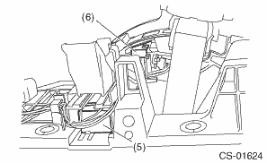
1. MODEL WITHOUT PUSH BUTTON IGNITION SWITCH
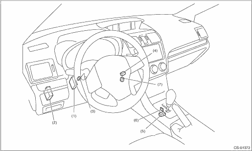
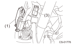
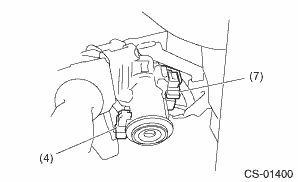
(1) | TCM (“P” range) | (4) | Key cylinder (with built-in key warning switch) | (6) | “P” range switch |
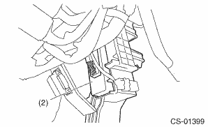
(2) | Body integrated unit | (5) | Solenoid unit | (7) | Key lock solenoid |
(3) | Stop light and brake switch |
2. MODEL WITH PUSH BUTTON IGNITION SWITCH
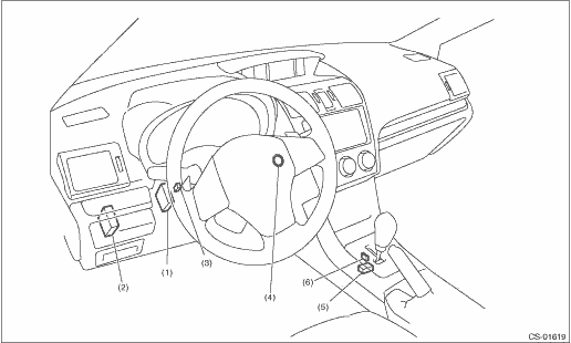
(1) | TCM (“P” range) | (3) | Stop light and brake switch | (5) | Solenoid unit |
(2) | Body integrated unit | (4) | Push button ignition switch | (6) | “P” range switch |

 Inspection
CONTROL SYSTEMS > AT Shift Lock Control SystemINSPECTION1. SHIFT LOCK OPERATION• Model without push button ignition switchSTEPCHECKYESNO1.CHECK COMMUNICATION OF SUBARU SELECT MONITOR.1) Turn ...
 Wiring diagram
CONTROL SYSTEMS > AT Shift Lock Control SystemWIRING DIAGRAM1. MODEL WITHOUT PUSH BUTTON IGNITION SWITCH(1)Ignition switch(5)TCM (shift range information)(9)Battery(2)Stop light and brake switch(6) ...
Other materials:
Dtc p0172 system too rich bank 1
ENGINE (DIAGNOSTICS)(H4DO) > Diagnostic Procedure with Diagnostic Trouble Code (DTC)DTC P0172 SYSTEM TOO RICH BANK 1DTC detecting condition:Detected when two consecutive driving cycles with fault occur.Trouble symptom:• Improper idling• Engine stall• Poor driving performanceCAUT ...
Rear view camera
A rear view camera is attached to the rear
gate. When the ignition switch is "ON" and
the shift lever (MT models) or select lever
(CVT models) is set to "R", the rear view
camera automatically displays the rear
view image behind the vehicle on one of
the following displays.
Navigation ...
Dtc p0017 crankshaft position - camshaft position correlation bank 1 sensor b
ENGINE (DIAGNOSTICS)(H4DO) > Diagnostic Procedure with Diagnostic Trouble Code (DTC)DTC P0017 CRANKSHAFT POSITION - CAMSHAFT POSITION CORRELATION BANK 1 SENSOR BDTC detecting condition:Detected when two consecutive driving cycles with fault occur.Trouble symptom:• Engine stall• Improp ...
