Subaru Crosstrek Service Manual: Wiring diagram
CONTROL SYSTEMS > AT Shift Lock Control System
WIRING DIAGRAM
1. MODEL WITHOUT PUSH BUTTON IGNITION SWITCH
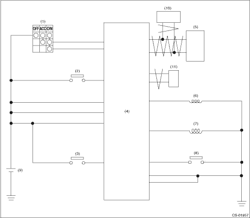
(1) | Ignition switch | (5) | TCM (shift range information) | (9) | Battery |
(2) | Stop light and brake switch | (6) | Key lock solenoid | (10) | ECM (delivery (test) mode signal) |
(3) | Key warning switch | (7) | Shift lock solenoid | (11) | VDC CM (vehicle speed information) |
(4) | Body integrated unit | (8) | “P” range switch |
2. MODEL WITH PUSH BUTTON IGNITION SWITCH
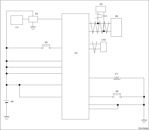
(1) | Keyless access CM | (5) | Body integrated unit | (8) | “P” range switch |
(2) | IG relay 1 (push button start) | (6) | TCM (shift range information) | (9) | ECM (delivery (test) mode signal) |
(3) | Stop light and brake switch | (7) | Shift lock solenoid | (10) | VDC CM (vehicle speed information) |
(4) | Battery |
 Location
CONTROL SYSTEMS > AT Shift Lock Control SystemLOCATION1. MODEL WITHOUT PUSH BUTTON IGNITION SWITCH(1)TCM (“P” range)(4)Key cylinder (with built-in key warning switch)(6)“P” ...

Other materials:
Dtc b28a2 eyesight communication(vdc)
EyeSight (DIAGNOSTICS) > Diagnostic Procedure with Diagnostic Trouble Code (DTC)DTC B28A2 EyeSight COMMUNICATION(VDC)Detected when the VDC control module (VDCCM) detects the malfunction of stereo camera.DTC DETECTING CONDITION:• Defective CAN system• Defective VDC control module (VDCC ...
Installation
POWER ASSISTED SYSTEM (POWER STEERING) > Steering WheelINSTALLATIONCAUTION:• Before handling the airbag system components, refer to “CAUTION” of “General Description” in “AIRBAG SYSTEM”. General Description > CAUTION">• If the steering w ...
How to contact the vehicle manufacturer
concerning modifications
for persons with disabilities that
may affect the advanced airbag
system
Changing or moving any parts of the front
seats, rear seat, seatbelts, front bumper,
front side frame, radiator panel, instrument
panel, combination meter, steering wheel,
steering column, tire, suspension or floor
panel can affect the operation of the
SUBARU advanced airbag system. If
you ha ...
