Subaru Crosstrek Service Manual: Installation
FUEL INJECTION (FUEL SYSTEMS)(H4DO) > Fuel Pump
INSTALLATION
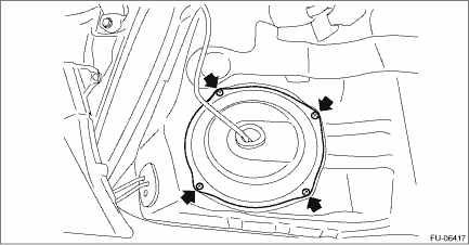
1. Install the fuel pump assembly to the fuel tank.
(1) Make sure the sealing portion is free from fuel or foreign matter before installation.
(2) Align the protrusion (A) of the gasket to the position shown in the figure, and install the gasket from the lower side of the fuel pump assembly.
NOTE:
Use a new gasket.
(3) Align the protrusion (C) of fuel pump upper plate cushion with the protrusion (C) of the fuel pump assembly as shown in the figure, and install the fuel pump upper plate cushion from the upper side of the fuel pump assembly.
(4) Align the cutout of the fuel pump upper plate with the protrusion (C), and install the fuel pump upper plate from the upper side of the fuel pump assembly so that the protrusions (B) (3 places) of the gasket fit the holes of the fuel pump upper plate.
(5) Install the fuel pump assembly to the fuel tank in the direction shown in the figure, and tighten the nuts to the specified torque in the order as shown in the figure.
CAUTION:
Set the arm and float of the fuel level sensor while paying attention to prevent them from contacting the fuel tank. If the arm of the fuel level sensor is bent, the fuel gauge may not read correctly.
Tightening torque:
4.4 N·m (0.4 kgf-m, 3.2 ft-lb)
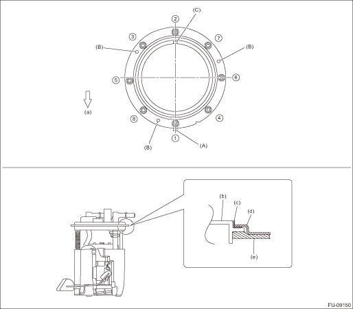
(a) | Front side of vehicle | (c) | Fuel pump upper plate cushion | (e) | Gasket |
(b) | Fuel pump ASSY | (d) | Fuel pump upper plate |
2. Connect the quick connector of the fuel delivery tube and the jet pump tube.
CAUTION:
• Check that there is no damage or dust on the quick connector. If necessary, clean the seal surface of the pipe.
• When connecting the quick connector, make sure to insert it all the way in before locking the slider.
• When it is difficult to lock the slider, check that the connector is fully inserted.
• After locking the slider, check again that the quick connector is securely connected.
NOTE:
Connect the quick connector as shown in the figure.
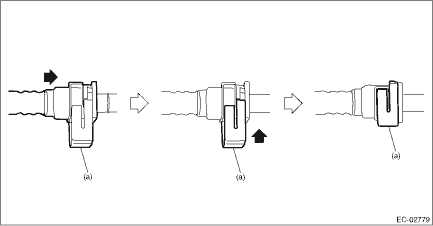
(a) | Slider |
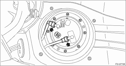
3. Connect the connector to the fuel pump.
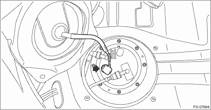
4. Install the service hole cover of fuel pump.
5. Install the rear seat cushion. Rear Seat > INSTALLATION">
6. Connect the battery ground terminal.
 Removal
FUEL INJECTION (FUEL SYSTEMS)(H4DO) > Fuel PumpREMOVALWARNING:Place “NO OPEN FLAMES” signs near the working area.CAUTION:• Be careful not to spill fuel.• Catch the fuel from ...
 Fuel pump relay
...
Other materials:
Climate control panel
WARNING
In the Subaru Ascent, the cooling function of the climate control system
operates only when the engine is running. Always ensure the engine is active
when relying on air conditioning.
Never leave children, dependent individuals, or pets unattended inside
the Subaru Ascent. On ...
Inspection
MECHANICAL(H4DO) > Cylinder BlockINSPECTION1. CYLINDER BLOCK & PISTON1. Visually inspect to make sure that there are no cracks, scratches or other damage.2. Use liquid penetrant tester on the important sections to check for fissures.3. Check that there are no traces of gas leaking or water le ...
Removal
GLASS/WINDOWS/MIRRORS > Front Door GlassREMOVAL1. Disconnect the ground cable from battery and wait for at least 60 seconds before starting work. NOTE">2. Remove the trim panel - front door. Door Trim > REMOVAL">3. Remove the sealing cover - front door. Front Sealing Cover & ...
