
Subaru Crosstrek Service Manual: Installation
FUEL INJECTION (FUEL SYSTEMS)(H4DO) > Fuel Filter
INSTALLATION
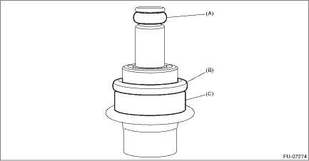
1. Install O-ring (A), O-ring (B), and backup ring (C) to the pressure regulator.
NOTE:
• Use new O-rings.
• Apply gasoline to the O-ring and backup ring.
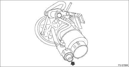
2. Install the pressure regulator to the fuel filter assembly.
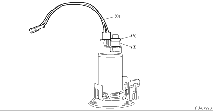
3. Install O-ring (A), spacer (B), and connector cable (C) to the fuel pump.
NOTE:
• Use new O-rings and the connector cable.
• Apply gasoline to the O-rings and the spacer.
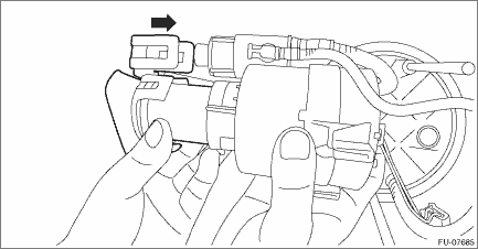
4. Install the fuel pump to the fuel filter assembly.
NOTE:
After installation, make sure five claws are correctly engaged in each position.
5. Check that the cushions of the fuel chamber assembly for dislocation. If any of them is dislocated, install a new cushion.
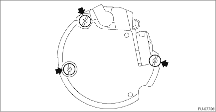
6. Slowly press in and install the tube assembly to the fuel chamber assembly until a clicking sound is heard.
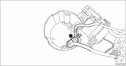
7. Connect the tube assembly to the fuel chamber assembly.

8. Install the fuel filter assembly to the fuel chamber assembly.
NOTE:
• Set the tube (A) and spring (B) for the fuel filter assembly as shown in the figure.
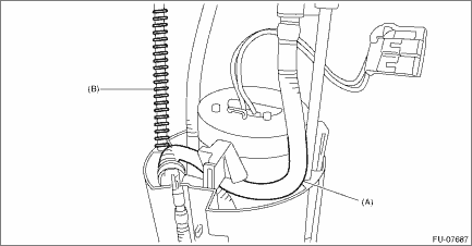
• Check that the claw connecting the fuel camber assembly and the fuel filter assembly is securely fastened.
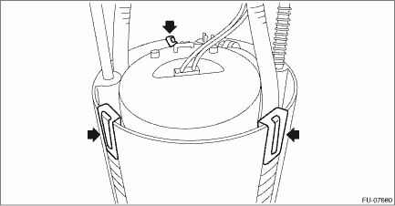
9. Push the fuel filter assembly in the direction of the arrow to compress, and attach the clip.
NOTE:
Use a new clip.
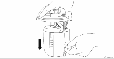
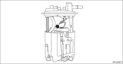
10. Secure the connector cable with the clip, and connect the connector (A) of the connector cable.
11. Install the fuel level sensor. Fuel Level Sensor > INSTALLATION">
12. Inspect the fuel level sensor. Fuel Level Sensor > INSPECTION">
13. Install the fuel pump assembly. Fuel Pump > INSTALLATION">
 Fuel filter
...
 Removal
FUEL INJECTION (FUEL SYSTEMS)(H4DO) > Fuel FilterREMOVALWARNING:Place “NO OPEN FLAMES” signs near the working area.CAUTION:• Be careful not to spill fuel.• If the fuel gauge ...
Other materials:
Inspection
LAN SYSTEM (DIAGNOSTICS) > General DescriptionINSPECTION1. INSPECTION WITHOUT USING CAN DIAGNOSTICBefore performing diagnosis, check the following items that might affect troubles of each module.1. Check the battery. Battery > INSPECTION">2. Check the fuse condition.Make sure that amp ...
Inspection
LAN SYSTEM (DIAGNOSTICS) > CAN Communication Circuit CheckINSPECTION1. GROUND SHORT INSPECTIONWiring diagram:CAN communication system CAN Communication System > WIRING DIAGRAM">• Without BSD/RCTA• With BSD/RCTANOTE:Main wiring harness or related lines may be shorted to gro ...
Activation of malfunction indicator light
ENGINE (DIAGNOSTICS)(H4DO) > Malfunction Indicator LightACTIVATION OF MALFUNCTION INDICATOR LIGHT1. When the ignition switch is turned to ON (engine OFF), the malfunction indicator light (A) in the combination meter illuminates.NOTE:If the malfunction indicator light does not illuminate, perform ...
