Subaru Crosstrek Service Manual: Removal
FUEL INJECTION (FUEL SYSTEMS)(H4DO) > Fuel Filter
REMOVAL
WARNING:
Place “NO OPEN FLAMES” signs near the working area.
CAUTION:
• Be careful not to spill fuel.
• If the fuel gauge indicates that two thirds or more of the fuel is remaining, be sure to drain fuel before starting work to avoid the fuel to spill.
• Be careful not to drop or apply any impact to the fuel pump during work. This may deteriorate its performance.
NOTE:
The fuel filter is built in fuel pump assembly.
1. Remove the fuel pump assembly. Fuel Pump > REMOVAL">
2. Remove the fuel level sensor. Fuel Level Sensor > REMOVAL">
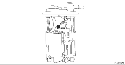
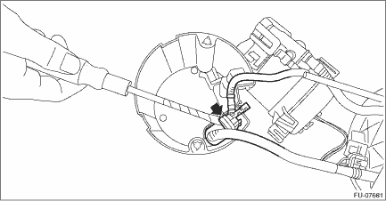
3. Remove the connector cable from the clip, and disconnect the connector (A) of the connector cable.
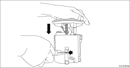
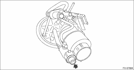
4. Push the fuel filter assembly in the direction of the arrow to compress, and detach the connecting clip.
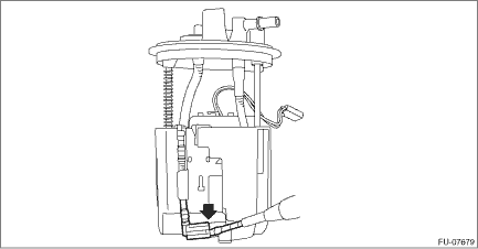
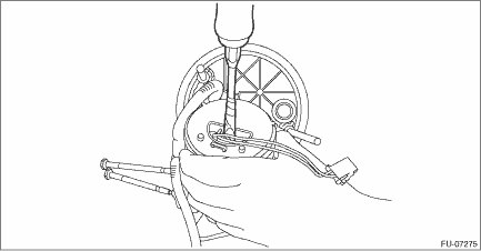
5. Release the claw using a flat tip screwdriver or similar tool wrapped with a protection tape, and remove the tube assembly from the fuel chamber assembly.
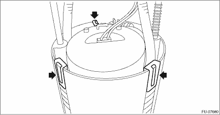
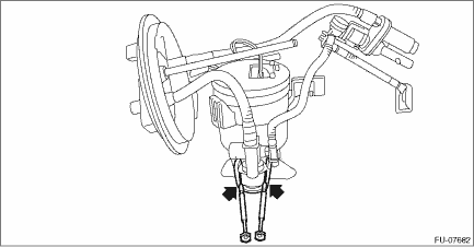
6. Release three claws on the fuel pump holder from the fuel chamber assembly, and raise the fuel filter assembly.
7. Using a flat tip screwdriver or similar tool wrapped with a protection tape, remove the tube assembly from the fuel chamber assembly, and separate the fuel filter assembly and fuel chamber assembly.
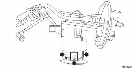
8. Using a precision driver or similar tool wrapped with a protection tape, expand the claws on the fuel pump.
9. Release the claws on the fuel pump.
10. Using a flat tip screwdriver or similar tool wrapped with a protection tape, press on the fuel pump and remove the fuel pump together with the fuel pump holder from the fuel filter assembly.
CAUTION:
If O-rings remain on the fuel filter assembly side, carefully remove them with a precision screwdriver or similar tool wrapped with a protection tape.
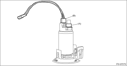
11. Remove the spacer (A) and connector cable (B) from the fuel pump.
12. Remove the pressure regulator from the fuel filter assembly.
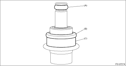
13. Remove O-ring (A), O-ring (B), and backup ring (C) from the pressure regulator.
 Installation
FUEL INJECTION (FUEL SYSTEMS)(H4DO) > Fuel FilterINSTALLATION1. Install O-ring (A), O-ring (B), and backup ring (C) to the pressure regulator.NOTE:• Use new O-rings.• Apply gasoline to ...
 Fuel injector
...
Other materials:
General scan tool Operation
ENGINE (DIAGNOSTICS)(H4DO) > General Scan ToolOPERATION1. HOW TO USE GENERAL SCAN TOOL1. Prepare a scan tool (general scan tool) required by SAE J1978.2. Connect the general scan tool to data link connector located in the lower portion of the instrument panel (on the driver’s side).3. Using ...
To hook the top tether
CAUTION
Except for the center seating
position, remove the head restraint
when mounting a child
restraint system. Otherwise, it
might be possible that the top
tether cannot be fastened tightly.
For the center seating position,
raise the center head restraint to
the extended posit ...
34
CRUISE CONTROL SYSTEM (DIAGNOSTICS) > Diagnostic Procedure with Cancel Code34The vehicle has been driven at a speed higher than set speed for a long time (approximately 10 minutes) during cruise driving.This cancel code is detected when driving for a long period of time at a speed higher than app ...
