Subaru Crosstrek Service Manual: Installation
DRIVE SHAFT SYSTEM > Rear Axle
INSTALLATION
1. Temporarily tighten the rear axle housing to the upper arm assembly.
2. Install the rear drive shaft assembly.
CAUTION:
• Do not hammer the drive shaft assembly when installing.
• Use new axle nuts.
(1) Insert the drive shaft assembly into the hub spline, and pull it into the specified position.
(2) Tighten the axle nut temporarily.
3. Tighten the rear strut assembly, rear stabilizer link and other links to the specified torque.
Tightening torque:
Rear suspension: General Description > COMPONENT">
Rear strut: General Description > COMPONENT">
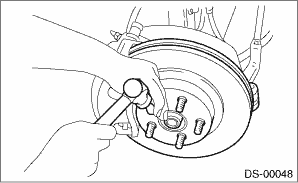
4. Install the rear disc rotor.
5. Install the caliper body assembly.
Tightening torque:
Refer to “COMPONENT” of “General Description” for the tightening torque. General Description > COMPONENT">
6. Install the brake hose bracket and rear ABS wheel speed sensor.
Tightening torque:
Brake hose bracket: 33 N·m (3.4 kgf-m, 24.3 ft-lb)
Rear ABS wheel speed sensor: 7.5 N·m (0.8 kgf-m, 5.5 ft-lb)
7. Install the sensor assembly - headlight beam leveler. (Model with auto headlight beam leveler)
Tightening torque:
7.5 N·m (0.8 kgf-m, 5.5 ft-lb)
8. While pressing the brake pedal, tighten the new axle nuts to the specified torque.
CAUTION:
Do not load the rear axle before tightening the axle nut. Doing so may damage the hub unit bearing.
Tightening torque:
190 N·m (19.4 kgf-m, 140.1 ft-lb)
9. After tightening the axle nut, lock it securely.
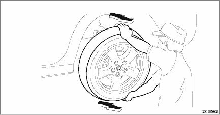
10. Install the rear wheels, and perform the following inspections.
Tightening torque:
Except for C4 model: 120 N·m (12.2 kgf-m, 88.5 ft-lb)
C4 model: 100 N·m (10.2 kgf-m, 73.8 ft-lb)
(1) Check the wheels for smooth rotation.
(2) Check that there is no looseness by moving the upper and lower portions of rear tire in an axial direction with the brake pedal released.
• Looseness exists > Check the rear hub unit bearing. Rear Hub Unit Bearing > INSPECTION">
11. Inspect the wheel alignment and adjust if necessary.
• Inspection: Wheel Alignment > INSPECTION">
• Adjustment: Wheel Alignment > ADJUSTMENT">
12. Perform reinitialization of the auto headlight beam leveler system. (Model with auto headlight beam leveler) Auto Headlight Beam Leveler System > PROCEDURE">
 Disassembly
DRIVE SHAFT SYSTEM > Rear AxleDISASSEMBLY1. BUSHING - REAR AXLE HOUSINGDo not remove the bushing - rear axle housing from the rear axle housing, because it cannot be replaced. If removed, replace t ...
 Rear drive shaft
...
Other materials:
Component
SEAT BELT SYSTEM > General DescriptionCOMPONENT1. FRONT SEAT BELT(1)Adjuster ASSY - seat belt(4)Seat belt inner - frontTightening torque: N·m (kgf-m, ft-lb)(2)Cover through(5)Wave washerT1:7.5 (0.76, 5.5)(3)Seat belt outer - front (only on passenger’s side with lap seat belt pretensi ...
Forced drive
SUNROOF/T-TOP/CONVERTIBLE TOP (SUNROOF) > Glass LidFORCED DRIVEIf the lid assembly - sunroof does not operate or the motor assembly is not supplied with power, move the lid assembly - sunroof using the hexagon wrench.Preparation tool:Hexagon wrench: width across flat 4 mm (0.16 in)CAUTION:After a ...
Connecting a Bluetooth device
To use the Bluetooth audio system, it is
necessary to register a Bluetooth device
with the system.
Registering an additional device
1. Select the "Add" key on the Bluetooth
devices connection screen.
2. For more information: Refer to "Registering/
connecting Bluetoothdevice" F5-
65.
Se ...
