
Subaru Crosstrek Service Manual: Installation
DRIVE SHAFT SYSTEM > Propeller Shaft
INSTALLATION
1. Before installation, check the following items, and replace the propeller shaft assembly as necessary.
• Dents or cracks on the tube surface
• Splines for deformation or abnormal wear
• Unsmooth joint operation or abnormal noise
• Center bearing for free play, noise or non-smooth operation.
• Oil seals for abnormal wear or damage
• Damaged center bearing
2. Apply fluid or gear oil to the oil seal lip and the propeller shaft.
• CVT model: SUBARU CVT OIL FOR LINEARTRONIC
• MT model: GL-5
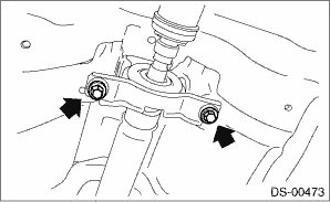
3. Insert the sleeve yoke into the transmission and attach center bearing to body.
Tightening torque:
52 N·m (5.3 kgf-m, 38.4 ft-lb)
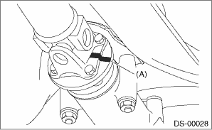
4. Align the alignment marks (A), and connect the yoke flange and rear differential.
Tightening torque:
31 N·m (3.2 kgf-m, 22.9 ft-lb)
5. Check the propeller shaft with the propeller shaft installed to the vehicle. Propeller Shaft > INSPECTION">
6. Install the center exhaust cover.
Tightening torque:
18 N·m (1.8 kgf-m, 13.3 ft-lb)
7. Install the center exhaust pipe, rear exhaust pipe and muffler.
• Center exhaust pipe & rear exhaust pipe: Rear Exhaust Pipe > INSTALLATION">
• Muffler: Muffler > INSTALLATION">
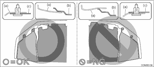
8. Install the under cover - front.
CAUTION:
Install so that the front end of the under cover (b) comes inside the bumper face - front (a), and the front end of the mud guard (c) comes outside the bumper face - front (a).
Tightening torque:
18 N·m (1.84 kgf-m, 13.3 ft-lb)
9. Lower the vehicle.
 Removal
DRIVE SHAFT SYSTEM > Propeller ShaftREMOVALCAUTION:• Before removing propeller shaft, wrap metal parts with a cloth or rubber material.• Do not disassemble the center EDJ of the propell ...
 Rear axle
...
Other materials:
Diagnostic procedure for subaru select monitor communication Communication for initializing impossible
HVAC SYSTEM (AUTO A/C) (DIAGNOSTICS) > Diagnostic Procedure for Subaru Select Monitor CommunicationCOMMUNICATION FOR INITIALIZING IMPOSSIBLEDiagnosis:Defective CAN communication circuitTrouble symptom:• LAN system is abnormal.• Communication failure between Subaru Select Monitor and A ...
Catalytic converter
The catalytic converter is installed in the
exhaust system. It serves as a catalyst to
reduce HC, CO and NOx in exhaust
gases, thus providing cleaner exhaust.
To avoid damage to the catalytic converter:
Use only unleaded fuel. Even a small
amount of leaded fuel will damage the
cata ...
Basic information before use
WARNING
When the vehicle is stopped with the
engine running, always apply the
parking brake for safety. Failure to
do so may result in loss of control of
your vehicle and cause an accident
or serious injury.
CAUTION
To prevent damaging the screen,
touch the screen keys with your
finge ...
