Subaru Crosstrek Service Manual: Installation
DRIVE SHAFT SYSTEM > Front Drive Shaft
INSTALLATION
1. Before installation, check the drive shaft assembly. Front Drive Shaft > INSPECTION">
2. Replace the differential side retainer oil seal with a new part.
• MT model: Differential Side Retainer Oil Seal > REPLACEMENT">
• CVT model: Differential Side Retainer Oil Seal > REPLACEMENT">
NOTE:
After pulling out the drive shaft assembly, be sure to replace with a new oil seal.
3. Insert the drive shaft assembly into the hub spline, and pull it into the specified position.
CAUTION:
Do not hammer the drive shaft assembly when installing.
4. Tighten the axle nut temporarily.
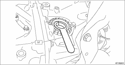
5. Using the ST, install the front drive shaft assembly to the transmission.
Preparation tool:
ST: OIL SEAL PROTECTOR (28399SA010)
6. Install the ball joint assembly to the front axle housing.
CAUTION:
Before tightening, make sure the lower side of front axle housing and stepped section of ball joint are in contact.
Tightening torque:
50 N·m (5.1 kgf-m, 36.9 ft-lb)
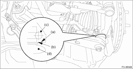
(a) | Lower side of front axle housing | (c) | Front axle housing | (d) | Ball joint |
(b) | Raised section of ball joint |
7. Install the stabilizer link.
Tightening torque:
60 N·m (6.1 kgf-m, 44.3 ft-lb)
8. While pressing the brake pedal, tighten the new axle nuts to the specified torque.
CAUTION:
Do not load the front axle before tightening the axle nut. Doing so may damage the hub unit bearing.
Tightening torque:
220 N·m (22.4 kgf-m, 162.3 ft-lb)
9. After tightening axle nut, lock it securely.
10. Fill transmission gear oil. (MT model)
11. Fill differential gear oil. (CVT model)
12. Install the front wheels.
Tightening torque:
Except for C4 model: 120 N·m (12.2 kgf-m, 88.5 ft-lb)
C4 model: 100 N·m (10.2 kgf-m, 73.8 ft-lb)
13. Inspect the wheel alignment and adjust if necessary.
• Inspection: Wheel Alignment > INSPECTION">
• Adjustment: Wheel Alignment > ADJUSTMENT">
CAUTION:
When the wheel alignment has been adjusted, perform “VDC sensor midpoint setting mode”. VDC Control Module and Hydraulic Control Unit (VDCCM&H/U) > ADJUSTMENT"> VDC Control Module and Hydraulic Control Unit (VDCCM&H/U) > ADJUSTMENT"> VDC Control Module and Hydraulic Control Unit (VDCCM&H/U) > ADJUSTMENT">
14. Perform reinitialization of the auto headlight beam leveler system. (Model with auto headlight beam leveler) Auto Headlight Beam Leveler System > PROCEDURE">
 Inspection
DRIVE SHAFT SYSTEM > Front Drive ShaftINSPECTIONCheck the removed parts for damage, wear, corrosion etc. If faulty, repair or replace.• PTJ (pillow tripod joint)Check for seizure, corrosion, ...

Other materials:
Automatic Locking Retractor/Emergency Locking Retractor (ALR/ELR)
Each passenger's seatbelt has an Automatic
Locking Retractor/Emergency Locking
Retractor (ALR/ELR). The Automatic
Locking Retractor/Emergency Locking
Retractor normally functions as an Emergency
Locking Retractor (ELR). The ALR/
ELR has an additional locking mode
"Automatic Locking Retractor ...
Symbols in wiring diagrams
WIRING SYSTEM > Basic Diagnostic ProcedureSYMBOLS IN WIRING DIAGRAMSA number of symbols are used in each wiring diagram to easily identify parts or circuits.1. RELAYA symbol used to indicate a relay.2. CONNECTOR 1The sketch of the connector indicates the one-pole types.3. WIRING CONNECTIONSome wi ...
Diagnostics with phenomenon Inspection
KEYLESS ACCESS WITH PUSH BUTTON START SYSTEM (DIAGNOSTICS) > Diagnostics with PhenomenonINSPECTION1. KEYLESS ACCESS LOCK/UNLOCK CANNOT BE PERFORMED FROM ANY OF THE DOORSCAUTION:• Check that there are no other registered access keys inside the vehicle.• Inspect LAN system according to ...
