Subaru Crosstrek Service Manual: Installation
CONTINUOUSLY VARIABLE TRANSMISSION(TR580) > Transmission Case
INSTALLATION
1. Clean the mating surface of transmission case and converter case.
2. Select the reduction gear shim. Reduction Drive Gear > ADJUSTMENT">
3. Remove the transmission case, and install the selected reduction gear shim to the reduction drive gear.
4. Install the O-rings to the reverse clutch housing and drive pinion retainer.
NOTE:
• Use new O-rings.
• Apply CVTF to the O-rings.
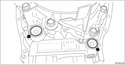
5. Install the seal ring to the transmission case.
NOTE:
• Use new seal rings.
• When installing the seal rings, do not expand the seal rings too much.
• Apply CVTF to the seal rings.
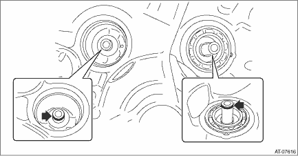
6. Cover the secondary pulley with the oil baffle, and temporarily install it with bolts.
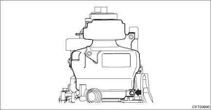
7. Apply liquid gasket seamlessly to the mating surface of transmission case.
Liquid gasket:
THREE BOND 1215B or equivalent
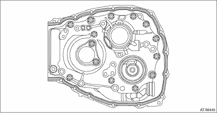
8. Install the transmission case.
NOTE:
The total number of transmission case mounting bolts is 15.
Tightening torque:
22 N·m (2.2 kgf-m, 16.2 ft-lb)
9. Install the oil cooler pipe.
NOTE:
Use new O-rings.
Tightening torque:
25 N·m (2.5 kgf-m, 18.4 ft-lb)
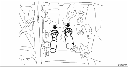
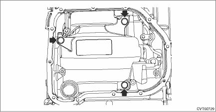
10. Install the oil baffle securing bolt.
Tightening torque:
16 N·m (1.6 kgf-m, 11.8 ft-lb)
11. Install the transmission control device. Transmission Control Device > INSTALLATION">
12. Install the oil pan and oil strainer. Oil Pan and Strainer > INSTALLATION">
13. Install the reduction driven gear assembly. Reduction Driven Gear > INSTALLATION">
14. Install the parking pawl. Parking Pawl > INSTALLATION">
15. Install the transfer driven gear assembly. Transfer Driven Gear > INSTALLATION">
16. Install the transfer clutch assembly. Transfer Clutch > INSTALLATION">
17. Install the extension case. Extension Case > INSTALLATION">
18. Install the inhibitor switch. Inhibitor Switch > INSTALLATION">
19. Install the secondary speed sensor. Secondary Speed Sensor > INSTALLATION">
20. Install the primary speed sensor. Primary Speed Sensor > INSTALLATION">
21. Install the turbine speed sensor. Turbine Speed Sensor > INSTALLATION">
22. Install the transmission harness. Transmission Harness > INSTALLATION">
23. Install the control valve body. Control Valve Body > INSTALLATION">
24. Install the air breather hose. Air Breather Hose > INSTALLATION">
25. Install the transmission assembly to the vehicle. Automatic Transmission Assembly > INSTALLATION">
 Inspection
CONTINUOUSLY VARIABLE TRANSMISSION(TR580) > Transmission CaseINSPECTION• Check the transmission case for damage.• Check for leakage of CVTF from the connection between converter case an ...
Other materials:
Inspection
GLASS/WINDOWS/MIRRORS > Front Regulator and Motor AssemblyINSPECTION1. Disconnect the connector of the motor - front.2. Check the motor operation when battery voltage is applied between terminals of the motor - front connector.• LH sideTerminal No.Inspection conditionsStandard4 (+) — 1 (& ...
Location
ENTERTAINMENT > Relay and FuseLOCATIONRelay & fuse boxFuse 20 A (rear accessory power supply socket)(A)Fuse 10 A (front accessory power supply socket)(B)Fuse 10 A (audio, navigation unit, AUX input terminal, data communication module*1)(C)Fuse 15 A (data communication module*1)(D)*1: Model wi ...
List of diagnostic trouble code (dtc) List
POWER ASSISTED SYSTEM (POWER STEERING) (DIAGNOSTICS) > List of Diagnostic Trouble Code (DTC)LISTDTCItemContent of diagnosisNoteNoneWithout DTCNormal Subaru Select Monitor > INSPECTION">“Assist limitation” is displayed in the current data «EPS operating condition».Assist l ...

