Subaru Crosstrek Service Manual: Dtc c1562 reverse on fault
VEHICLE DYNAMICS CONTROL (VDC) (DIAGNOSTICS) > Diagnostic Procedure with Diagnostic Trouble Code (DTC)
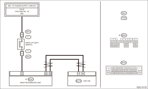
DTC C1562 REVERSE ON FAULT
DTC detecting condition:
Abnormal reverse signal
Trouble symptom:
Hill start assist does not operate.
Wiring diagram:
Back-up light system Back-up Light System">
CAN communication system CAN Communication System">
| STEP | CHECK | YES | NO |
1.CHECK LAN SYSTEM.
Perform the diagnosis for LAN system. Basic Diagnostic Procedure">
Is there any fault in LAN system?
Perform the diagnosis according to DTC for LAN system. List of Diagnostic Trouble Code (DTC)">
Diagnostic Procedure with Diagnostic Trouble Code (DTC) > DTC C1562 REVERSE ON FAULT">Go to Step 2.
2.CHECK REVERSE SIGNAL USING SUBARU SELECT MONITOR.
1) Using the Subaru Select Monitor, select “Data monitor”. Subaru Select Monitor > OPERATION">
2) Read the «Reverse Signal» displayed on display.
Is “OFF” displayed when the shift lever is placed in any position other than reverse, and is “ON” displayed in reverse position?
Diagnostic Procedure with Diagnostic Trouble Code (DTC) > DTC C1562 REVERSE ON FAULT">Go to Step 5.
Diagnostic Procedure with Diagnostic Trouble Code (DTC) > DTC C1562 REVERSE ON FAULT">Go to Step 3.
3.CHECK BACK-UP LIGHT ILLUMINATION.
1) Turn the ignition switch to ON.
2) Place the shift lever in reverse position.
Does the back-up light illuminate?
Diagnostic Procedure with Diagnostic Trouble Code (DTC) > DTC C1562 REVERSE ON FAULT">Go to Step 4.
Repair the back-up light circuit.
4.CHECK HARNESS BETWEEN BODY INTEGRATED UNIT AND BACK-UP LIGHT SWITCH (CHECK FOR OPEN CIRCUIT).
1) Turn the ignition switch to OFF.
2) Disconnect the connectors from body integrated unit and back-up light switch.
3) Measure the resistance of harness between body integrated unit and back-up light switch connector.
Connector & terminal
(B281) No. 12 — (B24) No. 1:
Is the resistance less than 1 ??
Replace the back-up light switch. Switches and Harness">
Repair the harness between body integrated unit and back-up light switch connector.
5.CHECK VDCCM&H/U.
1) Connect all connectors.
2) Perform the Clear Memory Mode. Clear Memory Mode">
3) Perform the Inspection Mode. Inspection Mode">
4) Read the DTC. Read Diagnostic Trouble Code (DTC)">
Is the same DTC displayed?
Replace the VDCCM only. VDC Control Module and Hydraulic Control Unit (VDCCM&H/U) > REPLACEMENT">
Diagnostic Procedure with Diagnostic Trouble Code (DTC) > DTC C1562 REVERSE ON FAULT">Go to Step 6.
6.CHECK DETECTION OF OTHER DTCS FOR VDC.
Read Diagnostic Trouble Code (DTC)">
Is any other DTC displayed?
Perform the diagnosis according to DTC. List of Diagnostic Trouble Code (DTC)">
Currently, it is normal. There may have been a temporary poor contact in the harness and connector or a temporary noise interference.
 Dtc c1421 ecm control system
VEHICLE DYNAMICS CONTROL (VDC) (DIAGNOSTICS) > Diagnostic Procedure with Diagnostic Trouble Code (DTC)DTC C1421 ECM CONTROL SYSTEMDTC detecting condition:ECM malfunctioningTrouble symptom:• A ...
 Dtc c1561 reverse off fault
VEHICLE DYNAMICS CONTROL (VDC) (DIAGNOSTICS) > Diagnostic Procedure with Diagnostic Trouble Code (DTC)DTC C1561 REVERSE OFF FAULTNOTE:For the diagnostic procedure, refer to “DTC C1562 REVERSE ...
Other materials:
Starting engine
CAUTION
Do not operate the starter motor
continuously for more than 10 seconds.
If the engine fails to start after
operating the starter for 5 to 10
seconds, wait for 10 seconds or
more before trying again.
NOTE
It may be difficult to start the engine
when the battery has been disconnecte ...
Inspection
CONTINUOUSLY VARIABLE TRANSMISSION(TR580) > Forward Clutch AssemblyINSPECTION• Check the forward clutch drum, internal gear, sun gear and forward clutch piston lip for wear or damage.• Inspect the drive plate facing for wear and damage.• Check the driven plate for discoloration ...
Sonar Audible Alarm function
In the Subaru Ascent, the Reverse Automatic Braking (RAB) system is supported
by an advanced sonar audible alert function designed to enhance driver awareness.
When the system detects a potential obstacle while reversing, it emits warning sounds
in three distinct intensity levels, helping the ...
