
Subaru Crosstrek Service Manual: Installation
CONTINUOUSLY VARIABLE TRANSMISSION(TR580) > Inhibitor Switch
INSTALLATION
1. Install the inhibitor switch to the transmission case temporarily.
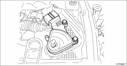
2. Connect the inhibitor harness connector to the inhibitor switch.
3. Install the shifter arm and fix with the spring pin.
NOTE:
Use new spring pin.
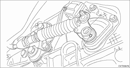
(A) | Spring pin |
(B) | Shifter arm |
4. Shift the shifter arm to “N” range.
5. Install the ST vertically in the cutout of shifter arm and the hole of switch body.
| ST 499267300 | STOPPER PIN |
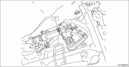
6. Tighten the two bolts holding the inhibitor switch.
Tightening torque:
5 N·m (0.5 kgf-m, 3.7 ft-lb)
7. Install the select cable to the shifter arm.
8. Install the washer and snap pin to the shifter arm.
CAUTION:
Do not apply extra overload while holding the part (A).
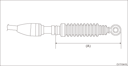
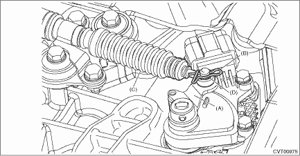
(A) | Shifter arm |
(B) | Snap pin |
(C) | Select cable |
(D) | Washer |
9. Install the center exhaust pipe. Center Exhaust Pipe > INSTALLATION">
10. Lower the vehicle.
11. Connect the battery ground terminal.
12. Check the inhibitor switch. Inhibitor Switch > INSPECTION">
 Inspection
CONTINUOUSLY VARIABLE TRANSMISSION(TR580) > Inhibitor SwitchINSPECTIONWhen the driving condition or starter motor operation is improper, first check the shift linkage for improper operation. If the ...

Other materials:
ABS (Anti-lock Brake System)
The ABS prevents the lock-up of wheels
which may occur during sudden braking or
braking on slippery road surfaces. This
helps prevent the loss of steering control
and directional stability caused by wheel
lock-up.
When the ABS is operating, you may hear
a chattering noise or feel a slight v ...
Removal
FUEL INJECTION (FUEL SYSTEMS)(H4DO) > Throttle BodyREMOVAL1. Disconnect the ground cable from battery.2. Lift up the vehicle.3. Remove the under cover. Front Under Cover > REMOVAL">4. Drain approximately 3.0 L (3.2 US qt, 2.6 Imp qt) of coolant. Engine Coolant > REPLACEMENT"& ...
Seatbelt pretensioners
The Subaru Ascent is equipped with advanced seatbelt pretensioner systems that
significantly enhance occupant protection in the event of a collision. These systems
are designed to instantly tighten the seatbelt, reducing slack and ensuring that
passengers are securely restrained at the moment ...
