Subaru Crosstrek Service Manual: Inspection
SPEED CONTROL SYSTEMS(H4DO) > Accelerator Pedal
INSPECTION
1. CHECK ACCELERATOR PEDAL SENSOR AREA (METHOD WITH CIRCUIT TESTER)
1. Remove the glove box. Glove Box > REMOVAL">
2. Turn the ignition switch to ON. (Engine OFF)
3. Measure the voltage between ECM connector terminals.
• Main sensor side
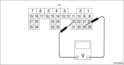
(A) | To ECM connector |
• Sub sensor side
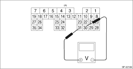
(A) | To ECM connector |
Accelerator pedal sensor | Accelerator pedal | Terminal No. | Standard |
Main | Not depressed (full closed) | 23 (+) and 29 (−) | 0.4 — 1.0 V |
Depressed (full opened) | 2.4 — 3.7 V | ||
Sub | Not depressed (full closed) | 31 (+) and 30 (−) | 0.3 — 1.1 V |
Depressed (full opened) | 2.3 — 3.8 V |
4. After inspection, install the related parts in the reverse order of removal.
2. CHECK ACCELERATOR PEDAL SENSOR AREA (METHOD WITH SUBARU SELECT MONITOR)
1. Turn the ignition switch to ON. (Engine OFF)
2. Read the accelerator pedal opening angle signal and voltage of accelerator pedal sensor using Subaru Select Monitor. Subaru Select Monitor > OPERATION">
Accelerator pedal sensor | Accelerator pedal opening angle signal | Standard |
Main | 0.0% | 0.4 — 1.0 V |
100.0% | 2.4 — 3.7 V | |
Sub | 0.0% | 0.3 — 1.1 V |
100.0% | 2.3 — 3.8 V |
3. OTHER INSPECTIONS
1. Check that the accelerator pedal does not have deformation, cracks or damage.
2. Check for smooth operation when the accelerator pedal is depressed.
3. Check if the accelerator pedal returns to its original position smoothly when the pedal is released.
 Removal
SPEED CONTROL SYSTEMS(H4DO) > Accelerator PedalREMOVAL1. Disconnect the ground cable from battery. NOTE">2. Disconnect the connector (A).3. Remove the nut (B) securing accelerator pedal as ...
 Installation
SPEED CONTROL SYSTEMS(H4DO) > Accelerator PedalINSTALLATIONInstall in the reverse order of removal.Tightening torque:7.5 N·m (0.8 kgf-m, 5.5 ft-lb) ...
Other materials:
Dtc p0141 o2 sensor heater circuit bank 1 sensor 2
ENGINE (DIAGNOSTICS)(H4DO) > Diagnostic Procedure with Diagnostic Trouble Code (DTC)DTC P0141 O2 SENSOR HEATER CIRCUIT BANK 1 SENSOR 2Refer to DTC P0037 for diagnostic procedure. Diagnostic Procedure with Diagnostic Trouble Code (DTC) > DTC P0037 A/F / O2 HEATER CONTROL CIRCUIT LOW BANK 1 SEN ...
Read diagnostic trouble code (dtc) Operation
Blind Spot Detection/Rear Cross Traffic Alert (DIAGNOSTICS) > Read Diagnostic Trouble Code (DTC)OPERATION1. On «Start» display, select «Diagnosis».2. On «Vehicle selection» display, input the target vehicle information and select «Confirmed».3. On «Main Menu» display, select «Each Syst ...
Caution
CLUTCH SYSTEM > General DescriptionCAUTION• Remove contamination including dirt and corrosion before removal, installation or disassembly.• Keep the disassembled parts in order and protect them from dust and dirt.• Before removal, installation or disassembly, be sure to clarify ...
