Subaru Crosstrek Service Manual: Inspection
POWER ASSISTED SYSTEM (POWER STEERING) > Electric Power Steering Gearbox
INSPECTION
1. UNIT INSPECTION
Check components for wear, damage or other faults. Adjust or replace if necessary.
2. LIMIT
Make a measurements as follows. If it exceeds the specified service limits, adjust or replace.
NOTE:
When fixing the steering gearbox assembly in a vise, apply a wooden piece on the flange portion.
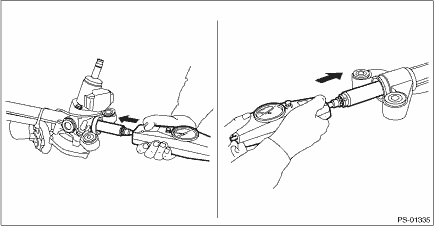
Rack shaft sliding resistance:
Limit: 303 N (31 kgf, 68 lbf) or less
Left/right differential of sliding resistance: 20% or less
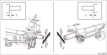
3. RACK SHAFT PLAY IN THE RADIAL DIRECTION
NOTE:
• When fixing the steering gearbox assembly in a vise, apply a wooden piece on the flange portion.
• When fixing the magnet stand in the steering gearbox assembly, perform the following procedure.
– Fix the iron plate on the flange portion using a c-clamp, and place the magnet stand on the iron plate.
– Use bolts and nuts to fix directly on the flange portion of the steering gearbox assembly. (Secure the gauge firmly on the gearbox body. (Avoid the input shaft and the rack shaft.))
Right-turn steering:
Service limit:
Both amplitudes: 0.6 mm (0.024 in) or less
Left-turn steering:
Service limit:
Both amplitudes: 0.6 mm (0.024 in) or less
Condition:
L: 5 mm (0.2 in) from dust cover
Rack shaft end P: 98 N (10 kgf, 22 lbf)
NOTE:
The location where the magnet stand is installed varies to stabilize the magnet stand.
4. INPUT SHAFT PLAY
NOTE:
• When fixing the steering gearbox assembly in a vise, apply a wooden piece on the flange portion.
• When fixing the magnet stand in the steering gearbox assembly, perform the following procedure.
– Fix the iron plate on the flange portion using a c-clamp, and place the magnet stand on the iron plate.
– Use bolts and nuts to fix directly on the flange portion of the steering gearbox assembly. (Secure the gauge firmly on the gearbox body. (Avoid the input shaft and the rack shaft.))
In radial direction:
Limit: Both amplitudes: 0.6 mm (0.024 in) or less
Condition: Input shaft tip P = 98 N (10 kgf, 22 lbf)
In axial direction:
Limit: 0.27 mm (0.0106 in) or less
Condition: Input shaft tip P = 20 — 49 N (2 — 5 kgf, 4 — 11 lbf)
NOTE:
The location where the magnet stand is installed varies to stabilize the magnet stand.
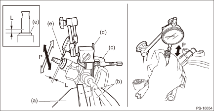
(a) | Vise | (c) | C-clamp | (e) | Dust cover |
(b) | Wooden block | (d) | Iron plate |
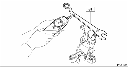
5. TURNING RESISTANCE OF GEARBOX
1. Using the ST, measure the rotational resistance of the steering gearbox assembly.
Preparation tool:
ST: SPANNER (34099PA100)
Service limit:
Maximum allowable resistance: 18.0 N (1.8 kgf, 4.0 lbf) or less
Difference between right and left rotational resistance: 20% or less
 Disassembly
POWER ASSISTED SYSTEM (POWER STEERING) > Electric Power Steering GearboxDISASSEMBLYCAUTION:• Nut for fixing the rack is on the driver’s side only. When removing the tie-rod on the passe ...
 Installation
POWER ASSISTED SYSTEM (POWER STEERING) > Electric Power Steering GearboxINSTALLATION1. Insert the steering gearbox assembly into crossmember, being careful not to damage the boot of the steering ge ...
Other materials:
Canceling the function for meter/gauge needle movement upon turning on the
ignition switch
It is possible to activate or deactivate the
movement of the meter needles and
gauge needles that takes place when the
ignition switch is turned to the "ON"
position.
Type A combination meter
To change the setting, perform the following
procedure.
1. Turn the ignition switch to the "LOCK"/ ...
Dtc b28af stereo camera adjustment incomplete
EyeSight (DIAGNOSTICS) > Diagnostic Procedure with Diagnostic Trouble Code (DTC)DTC B28AF STEREO CAMERA ADJUSTMENT INCOMPLETEDetected when adjustment or inspection of stereo camera has not been completed normally.DTC DETECTING CONDITION:• Operation is aborted during adjustment or inspection ...
Dtc p2610 ecm/pcm engine off timer performance
ENGINE (DIAGNOSTICS)(H4DO) > Diagnostic Procedure with Diagnostic Trouble Code (DTC)DTC P2610 ECM/PCM ENGINE OFF TIMER PERFORMANCEDTC DETECTING CONDITION:Detected when two consecutive driving cycles with fault occur.CAUTION:After servicing or replacing faulty parts, perform Clear Memory Mode Cle ...
