Subaru Crosstrek Service Manual: Installation
POWER ASSISTED SYSTEM (POWER STEERING) > Electric Power Steering Gearbox
INSTALLATION
1. Insert the steering gearbox assembly into crossmember, being careful not to damage the boot of the steering gearbox assembly.
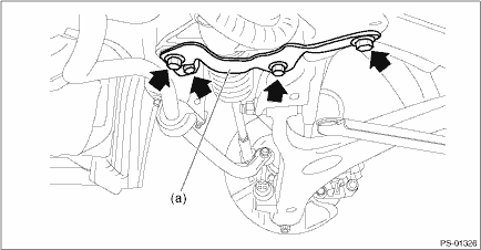
2. Install the steering gearbox assembly to the crossmember by tightening the bolts through the stiffener (a) to the specified torque.
Tightening torque:
60 N·m (6.12 kgf-m, 44.3 ft-lb)
3. Install the universal joint assembly - steering. Universal Joint > INSTALLATION">
CAUTION:
Tighten the bolts of the universal joint assembly - steering in the order of steering gearbox side and column shaft side.
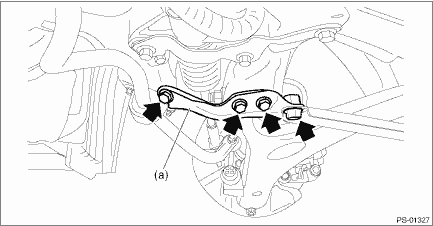
4. Install the support plate - front crossmember (a).
Tightening torque:
Support plate - front crossmember: 60 N·m (6.12 kgf-m, 44.3 ft-lb)
Front support: 100 N·m (10.20 kgf-m, 73.8 ft-lb)
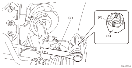
5. Connect the tie-rod ends and knuckle arm.
(1) Connect the tie-rod end (a) to the housing assembly - front axle.
(2) Tighten the castle nuts (b) to the specified torque.
CAUTION:
During connection, do not hit the cap at bottom of tie-rod end with a hammer.
Castle nut tightening torque:
27 N·m (2.75 kgf-m, 19.9 ft-lb)
(3) Tighten within the range of 60° so that the cotter pin hole and cutout portion of the castle nut (b) are aligned.
(4) Insert the cotter pin (c), and bend the tip of the pin to fix it.
6. Install the front crossmember - support.
Tightening torque:
60 N·m (6.12 kgf-m, 44.3 ft-lb)
7. Install the front exhaust pipe assembly. Front Exhaust Pipe > INSTALLATION">
8. Install the under cover - front. Front Under Cover > INSTALLATION">
9. Install the front wheels.
10. Lower the vehicle.
11. Tighten the wheel nuts to the specified torque.
Tightening torque:
Except for C4 model: 120 N·m (12.24 kgf-m, 88.5 ft-lb)
C4 model: 100 N·m (10.20 kgf-m, 73.8 ft-lb)
12. Connect the power steering control module harness connector.
13. Connect the battery ground terminal.
CAUTION:
When the wheel alignment has been adjusted, perform the adjustment of the steering angle sensor.
– Model without EyeSight: VDC sensor midpoint setting mode VDC Control Module and Hydraulic Control Unit (VDCCM&H/U) > ADJUSTMENT">
– Model with EyeSight: Neutral of Steering Angle Sensor & Lateral G Sensor 0 point setting VDC Control Module and Hydraulic Control Unit (VDCCM&H/U) > ADJUSTMENT">
– Model with EyeSight: Longitudinal G sensor & lateral G sensor 0 point setting VDC Control Module and Hydraulic Control Unit (VDCCM&H/U) > ADJUSTMENT">
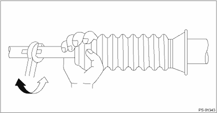
14. After adjusting toe-in and steering angle, tighten the lock nut on tie-rod end.
Tightening torque:
85 N·m (8.67 kgf-m, 62.7 ft-lb)
NOTE:
When adjusting toe-in, hold the boot - steering gearbox as shown to prevent it from being rotated or twisted. If it becomes twisted, straighten it.
 Inspection
POWER ASSISTED SYSTEM (POWER STEERING) > Electric Power Steering GearboxINSPECTION1. UNIT INSPECTIONCheck components for wear, damage or other faults. Adjust or replace if necessary.2. LIMITMake a ...

Other materials:
Clear memory mode Operation
TIRE PRESSURE MONITORING SYSTEM (DIAGNOSTICS) > Clear Memory ModeOPERATION1. On «Start» display, select «Diagnosis».2. On «Vehicle selection» display, input the target vehicle information and select «Confirmed».3. On «Main Menu» display, select «Each System».4. On «Select System» di ...
Dtc u0140 lost communication with body control module
EyeSight (DIAGNOSTICS) > Diagnostic Procedure with Diagnostic Trouble Code (DTC)DTC U0140 LOST COMMUNICATION WITH BODY CONTROL MODULEDetected when CAN data from body integrated unit is not transmitted to stereo camera.NOTE:Perform the diagnosis for LAN system. Basic Diagnostic Procedure > PRO ...
Dtc u0122 lost communication with vehicle dynamics control module
LAN SYSTEM (DIAGNOSTICS) > Diagnostic Procedure with Diagnostic Trouble Code (DTC)DTC U0122 LOST COMMUNICATION WITH VEHICLE DYNAMICS CONTROL MODULEDTC DETECTING CONDITION:No data from VDCCM is received.TROUBLE SYMPTOM:ABS warning light and VDC warning light illuminate.STEPCHECKYESNO1.CHECK PERFOR ...
