Subaru Crosstrek Service Manual: Inspection
LIGHTING SYSTEM > Light Control Sensor
INSPECTION
1. Turn the ignition switch to ON.
2. Set the lighting switch to AUTO position.
3. Check the voltage between the sensor terminals.
Preparation tool:
Circuit tester
Terminal No. | Inspection conditions | Standard | Connection diagram |
2 (+) — 1 (−) | Measure the voltage when the area around the sensor - automatic light, which was dark, becomes bright. | Dark condition: Approx. 0.6 V or less |
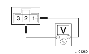
Bright condition: Approx. 3.0 V or more
4. Replace the sensor - automatic light if the inspection result is not within the standard value.

 Removal
LIGHTING SYSTEM > Light Control SensorREMOVAL1. Disconnect the ground cable from battery. NOTE">2. Remove the sensor - automatic light.CAUTION:Be careful not to damage the sensors and inte ...
Other materials:
Dtc b2a0a red led circuit
TELEMATICS SYSTEM (DIAGNOSTICS) > Diagnostic Procedure with Diagnostic Trouble Code (DTC)DTC B2A0A RED LED CIRCUITDiagnosis start condition:When ACC is ON.DTC detecting condition:• Current in LED is less than 1 mA. (Improper LED connection, etc.)• Current is more than 200 mA for at le ...
Dtc u0155 lost communication with instrument panel cluster (ipc) control module
TELEMATICS SYSTEM (DIAGNOSTICS) > Diagnostic Procedure with Diagnostic Trouble Code (DTC)DTC U0155 LOST COMMUNICATION WITH INSTRUMENT PANEL CLUSTER (IPC) CONTROL MODULEDetected when CAN data from combination meter does not arrive.NOTE:Perform the diagnosis for LAN system. Basic Diagnostic Proced ...
Inspection
POWER ASSISTED SYSTEM (POWER STEERING) > Steering ColumnINSPECTION1. UNIT INSPECTIONCheck the following items, and if there is anything out of standard value, it is considered to be damaged. If so, replace it with a new part.• Measure the whole length of the column assembly - steering.Stand ...
