
Subaru Crosstrek Service Manual: Inspection
LIGHTING SYSTEM > Hazard Switch
INSPECTION
1. Measure the resistance between connector terminals.
Preparation tool:
Circuit tester
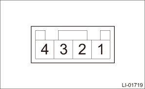
Terminal No. | Inspection conditions | Standard |
2 — 3 | Switch OFF | 1 M? or more |
Switch ON | Less than 1 ? |
2. Apply battery voltage between the connector terminals to check the lighting condition of the light.
Terminal No. | Inspection conditions | Specification |
4 (+) — 1 (−) | Apply battery voltage. | Light ON |
3. Replace the switch - hazard if the inspection result is not within the standard value.
 Hazard switch
...
 Removal
LIGHTING SYSTEM > Hazard SwitchREMOVAL1. Disconnect the ground cable from battery. NOTE">2. Remove the center grille assembly. Air Vent Grille > REMOVAL">3. Release the claws, ...
Other materials:
Dtc u0122 lost communication with vehicle dynamics control module
KEYLESS ACCESS WITH PUSH BUTTON START SYSTEM (DIAGNOSTICS) > Diagnostic Procedure with Diagnostic Trouble Code (DTC)DTC U0122 LOST COMMUNICATION WITH VEHICLE DYNAMICS CONTROL MODULEDetected when CAN data from VDC does not arrive.NOTE:Perform the diagnosis for LAN system. Basic Diagnostic Procedu ...
Electrical specification
AIRBAG SYSTEM (DIAGNOSTICS) > Airbag Control Module I/O SignalELECTRICAL SPECIFICATION• Terminal numbers in airbag control module connector are shown in the figure.• The airbag warning light illuminates when the connector is removed from the airbag control module.ItemControl module te ...
Engine overheating
WARNING
Never attempt to remove the radiator
cap until the engine has been
shut off and has fully cooled down.
When the engine is hot, the coolant
is under pressure. Removing the
cap while the engine is still hot
could release a spray of boiling hot
coolant, which could burn you very
seri ...
