Subaru Crosstrek Service Manual: Removal
ENTERTAINMENT > Antenna
REMOVAL
1. RADIO/TELEMATICS ANTENNA
CAUTION:
Before handling the airbag system components, refer to “CAUTION” of “General Description” in “AIRBAG SYSTEM”. General Description > CAUTION">
1. Disconnect the ground cable from battery and wait for at least 60 seconds before starting work. NOTE">
2. Remove the trim panel - roof assembly. Roof Trim > REMOVAL">
3. Remove the antenna assembly - radio or telematics.
(1) Disconnect the connector and terminal, and remove the mounting nut (A).
(2) Pull out the antenna assembly - radio or telematics from the roof panel top.
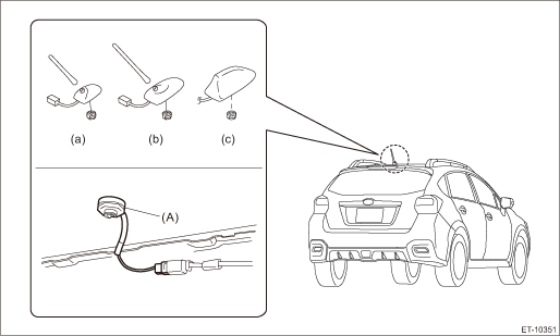
(a) | Radio antenna | (b) | XM radio antenna | (c) | Telematics antenna |
2. ANTENNA FEEDER CORD
CAUTION:
Before handling the airbag system components, refer to “CAUTION” of “General Description” in “AIRBAG SYSTEM”. General Description > CAUTION">
1. Disconnect the ground cable from battery and wait for at least 60 seconds before starting work. NOTE">
2. Remove the trim panel - roof assembly. Roof Trim > REMOVAL">
3. Remove the cover assembly - instrument panel LWR driver and the knee airbag module. Knee Airbag Module > REMOVAL">
4. Remove the glove box. Glove Box > REMOVAL">
5. Remove the center grille assembly. Air Vent Grille > REMOVAL">
6. Remove the audio assembly or navigation assembly. Audio > REMOVAL">
7. Turn over the floor mat. Floor Mat > REMOVAL">
8. Remove the cord assembly - antenna feeder.
3. TELEMATICS SUB ANTENNA
CAUTION:
Before handling the airbag system components, always refer to “CAUTION” of “General Description” in “AIRBAG SYSTEM”.
1. Disconnect the ground cable from battery and wait for at least 60 seconds before starting work. NOTE">
2. Remove the cover assembly - instrument panel LWR driver and the knee airbag module. Knee Airbag Module > REMOVAL">
3. Remove the glove box. Glove Box > REMOVAL">
4. Remove the center grille assembly. Air Vent Grille > REMOVAL">
5. Remove the audio assembly or navigation assembly. Audio > REMOVAL">
NOTE:
The data communication module will be removed at the same time.
6. Remove the combination meter assembly. Combination Meter > REMOVAL">
7. Remove the GPS antenna.
NOTE:
Remove the antenna only. Do not pull the cord.
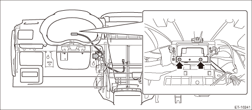
8. Remove the telematics sub antenna.
(1) Disconnect the telematics sub antenna connector on the data communication module side, and tie a string to the connector.
NOTE:
A string makes operation easier during installation.
(2) Remove the screw and harness clamp, and pull out the telematics sub antenna from the combination meter side.
(3) After the telematics sub antenna has been pulled out, remove the string attached to the connector in step (1).
 Installation
ENTERTAINMENT > AntennaINSTALLATIONCAUTION:• After installing the center grille assembly, check that the air vent grille of the center grille assembly is inserted correctly into the air vent ...
 Audio
Audio
...
Other materials:
Dtc b19f0 short in front p/t 2 rh
AIRBAG SYSTEM (DIAGNOSTICS) > Diagnostic Chart with Trouble CodeDTC B19F0 SHORT IN FRONT P/T 2 RHDiagnosis start condition:Ignition voltage is 10 V to 16 V.DTC detecting condition:• Lap seat belt pretensioner (RH) circuit is shorted.• Lap seat belt pretensioner (RH) is faulty.• ...
Removal
AIRBAG SYSTEM > Curtain Airbag SensorREMOVAL1. CROSSTREK MODELCAUTION:• Before handling the airbag system components, refer to “CAUTION” of “General Description” in “AIRBAG SYSTEM”. General Description > CAUTION">• Airbag system satellit ...
Installation
CONTINUOUSLY VARIABLE TRANSMISSION(TR580) > Extension CaseINSTALLATION1. Clean the mating surface of extension case and transmission case.2. Select the transfer drive gear shim. Reduction Drive Gear > ADJUSTMENT">3. Select the transfer driven gear shim. Transfer Clutch > ADJUSTMEN ...
