Subaru Crosstrek Service Manual: Inspection
FRONT SUSPENSION > Wheel Alignment
INSPECTION
Check the following items before performing the wheel alignment measurement.
• Tire inflation pressure
• Uneven wear of RH and LH tires, or difference of sizes
• Tire runout
• Excessive play and wear of ball joint
• Excessive play and wear of tie-rod end
• Excessive play of wheel bearing
• Right and left wheel base imbalance
• Deformation and excessive play of steering link
• Deformation and excessive play of suspension parts
Check, adjust and measure the wheel alignment in accordance with the following procedures.
1 | Wheel arch height (front and rear wheels) | Inspection: Wheel Alignment > INSPECTION"> |
↓ | ||
2 | Camber (front and rear wheels) | Inspection: Wheel Alignment > INSPECTION"> Adjustment: Wheel Alignment > ADJUSTMENT"> |
↓ | ||
3 | Caster (front wheel) | Inspection: Wheel Alignment > INSPECTION"> |
↓ | ||
4 | Adjustment of difference between right and left steering angles | Inspection: Wheel Alignment > INSPECTION"> Adjustment: Wheel Alignment > ADJUSTMENT"> |
↓ | ||
5 | Front wheel toe-in | Inspection: Wheel Alignment > INSPECTION"> Adjustment: Wheel Alignment > ADJUSTMENT"> |
↓ | ||
6 | Rear wheel toe-in | Inspection: Wheel Alignment > INSPECTION"> Adjustment: Wheel Alignment > ADJUSTMENT"> |
↓ | ||
7 | Thrust angle | Inspection: Wheel Alignment > INSPECTION"> Adjustment: Wheel Alignment > ADJUSTMENT"> |
1. WHEEL ARCH HEIGHT
1. Park the vehicle on a level surface.
2. Empty the vehicle so that it is at “curb weight”. (Empty the luggage compartment, load the spare tire, jack and service tools, and fill up the fuel tank.)
3. Set the steering wheel in a straight-ahead position, and stabilize the suspension by moving the vehicle in a straight line for 5 m (16 ft) or more.
4. Suspend a thread from the wheel arch (point “A” in the figure below) and affix at a position directly above the center of wheel.
5. Measure the distance between the point “A” and the center of wheel.
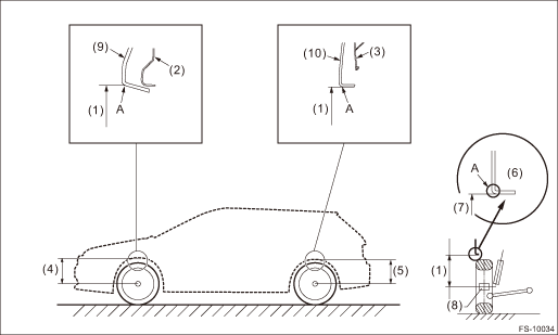
(1) | Wheel arch height | (5) | Rear wheel arch height | (9) | Garnish fender |
(2) | Front fender | (6) | Flange bend line | (10) | Garnish ASSY rear quarter |
(3) | Rear quarter | (7) | Point of measurement | ||
(4) | Front wheel arch height | (8) | End of spindle |
Wheel arch height specification mm (in) (tolerance: +12 mm −24 mm (+0.47 in −0.94 in)) | |
Tire size | P225/55R17 225/55R17 |
Front | 452 (17.8) |
Rear | 450 (17.72) |
2. CAMBER
1. Place the front wheel on the turning radius gauge.
NOTE:
Make sure the ground contact surfaces of the front and rear wheels are at the same height.
2. Set the adapter into the center of wheel, and then set the wheel alignment gauge.
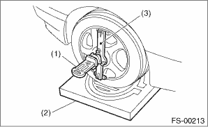
(1) | Alignment gauge |
(2) | Turning radius gauge |
(3) | Adapter |
3. Measure the camber angle in accordance with the operation manual for wheel alignment gauge.
Tire size | Camber (difference between RH and LH 45' or less) | |
P225/55R17 225/55R17 | 0°10'±0°45' | |
3. CASTER
1. Place the front wheel on the turning radius gauge. Make sure the ground contact surfaces of the front and rear wheels are at the same height.
2. Set the adapter into the center of wheel, and then set the wheel alignment gauge.
(1) | Alignment gauge |
(2) | Turning radius gauge |
(3) | Adapter |
3. Measure the caster angle in accordance with the operation manual for wheel alignment gauge.
Tire size | Caster | |
P225/55R17 225/55R17 | 5°60' | |
4. STEERING ANGLE
1. Place the vehicle on turning radius gauge.
2. While depressing the brake pedal, turn the steering wheel fully to the left and right.
3. With the steering wheel held at each fully turned position, measure both the inner and outer wheel steering angles.
Tire size | Inner wheel | Outer wheel |
P225/55R17 225/55R17 | 38.5°±1.5° | 34.0°±1.5° |
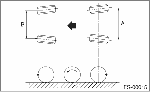
5. FRONT WHEEL TOE-IN
Toe-in: Inspection value
0±3 mm (0±0.12 in)
1. Set the toe-in gauge in the position at wheel axis center height behind the right and left front tires.
2. Place a mark at the center of both left and right tires, and measure distance “A” between the marks.
3. Move the vehicle forward to rotate the tires 180°.
NOTE:
Be sure to rotate the tires in the forward direction.
4. Measure the distance “B” between the left and right marks.
Find toe-in using the following calculation:
A − B = Toe-in
6. REAR WHEEL TOE-IN
Refer to the FRONT WHEEL TOE-IN for rear toe-in inspection procedures. Wheel Alignment > INSPECTION">
Toe-in: Inspection value
0±3 mm (0±0.12 in)
7. THRUST ANGLE
1. Park the vehicle on a level surface.
2. Move the vehicle 3 — 4 meters (10 — 13 feet) straight forward.
3. Draw the center of loci for both the front and rear axles.
4. Measure distance “L” between the center lines of the axle loci.
Thrust angle: Inspection value
0°±30'
Less than 30' when “L” is 23 mm (0.9 in) or less
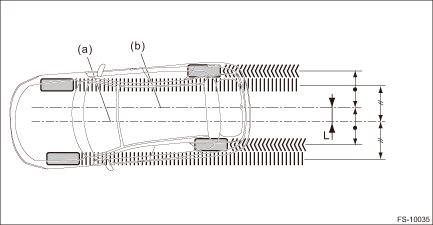
(a) | Center line of loci (front axle) | (b) | Center line of loci (rear axle) |
 Adjustment
FRONT SUSPENSION > Wheel AlignmentADJUSTMENTCAUTION:When the wheel alignment has been adjusted, perform the adjustment of the VDC. VDC Control Module and Hydraulic Control Unit (VDCCM&H/U) > ...
 General diagnostic table Inspection
FRONT SUSPENSION > General Diagnostic TableINSPECTION1. IMPROPER VEHICLE POSTURE OR IMPROPER WHEEL ARCH HEIGHTPossible causeCorrective action(1) Permanent distortion or damage of the coil springRep ...
Other materials:
Dtc c1733 longitudinal g sensor
VEHICLE DYNAMICS CONTROL (VDC) (DIAGNOSTICS) > Diagnostic Procedure with Diagnostic Trouble Code (DTC)DTC C1733 LONGITUDINAL G SENSORDTC DETECTING CONDITION:Defective longitudinal G sensorTROUBLE SYMPTOM:• ABS does not operate.• VDC does not operate.• Hill start assist does not ...
Dtc u0131 lost communication with power steering control module
LAN SYSTEM (DIAGNOSTICS) > Diagnostic Procedure with Diagnostic Trouble Code (DTC)DTC U0131 LOST COMMUNICATION WITH POWER STEERING CONTROL MODULEDTC DETECTING CONDITION:No data is received from power steering CM.TROUBLE SYMPTOM:Cooperation control with power steering CM does not operate properly. ...
Operation
GLASS/WINDOWS/MIRRORS > Power Window SystemOPERATION1. RESET OPERATION A1. Sit in the driver’s seat and close the door.2. Turn the ignition switch to ON.3. Operate the switch - power window main to open the glass assembly - front door halfway.4. Operate the switch - power window main in &ld ...
