Subaru Crosstrek Service Manual: Inspection
EyeSight (DIAGNOSTICS) > Subaru Select Monitor
INSPECTION
1. COMMUNICATION FOR INITIALIZING IMPOSSIBLE
• Communication error with stereo camera
DETECTING CONDITION:
• Defective harness connector
• Power supply circuit malfunction
• Defective stereo camera
• Defective CAN system
• Defective Subaru Select Monitor
TROUBLE SYMPTOM:
• EyeSight warning light blinks.
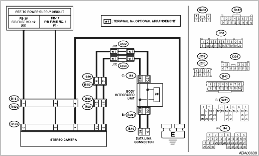
WIRING DIAGRAM:
EyeSight System EyeSight System > WIRING DIAGRAM">
| STEP | CHECK | YES | NO |
1.CHECK IGNITION SWITCH.
Is the ignition switch ON?
Subaru Select Monitor > INSPECTION">Go to Step 2.
Turn the ignition switch to ON, and select «EyeSight» using the Subaru Select Monitor.
2.CHECK BATTERY.
1) Turn the ignition switch to OFF.
2) Measure the battery voltage.
Is the voltage 10 V or more?
Subaru Select Monitor > INSPECTION">Go to Step 3.
Charge or replace the battery.
3.CHECK BATTERY TERMINAL.
Is the battery terminal contact proper?
Subaru Select Monitor > INSPECTION">Go to Step 4.
Connect the battery terminal securely or replace it.
4.CHECK SUBARU SELECT MONITOR COMMUNICATION.
1) Turn the ignition switch to ON.
2) Using the Subaru Select Monitor, check whether the communication can be executed normally.
Is the communication between Subaru Select Monitor and body integrated unit normal?
Subaru Select Monitor > INSPECTION">Go to Step 5.
Check the connection of the Subaru Select Monitor, and perform communication with the body integrated unit again.
5.READ DTC OF BODY INTEGRATED UNIT.
Select «Body Control», and check DTC.
Is any DTC other than “Lost Communication With EyeSight” detected?
Perform the diagnosis according to DTC.
Subaru Select Monitor > INSPECTION">Go to Step 6.
6.CHECK HARNESS CONNECTOR BETWEEN STEREO CAMERA AND DATA LINK CONNECTOR.
1) Turn the ignition switch to OFF.
2) Disconnect the stereo camera connector.
3) Measure the resistance between the stereo camera and the data link connector.
Connector & terminal
(R137) No. 10 — (B40) No. 6:
(R137) No. 9 — (B40) No. 14:
Is the resistance less than 10 ??
Subaru Select Monitor > INSPECTION">Go to Step 7.
Repair or replace the harness and connectors between the stereo camera and data link connector.
7.CHECK POWER SUPPLY CIRCUIT.
1) Turn the ignition switch to ON.
2) Measure the voltage between stereo camera and chassis ground.
Connector & terminal
(R137) No. 6 (+) — Chassis ground (−):
(R137) No. 8 (+) — Chassis ground (−):
Is the voltage 10 V or more?
Subaru Select Monitor > INSPECTION">Go to Step 8.
Repair or replace the harness and connectors between the stereo camera and fuse.
8.CHECK GROUND CIRCUIT.
1) Turn the ignition switch to OFF, then disconnect the ground cable from battery.
2) Measure the resistance between harness connector of stereo camera and chassis ground.
Connector & terminal
(R137) No. 7 — Chassis ground:
Is the resistance less than 10 ??
Subaru Select Monitor > INSPECTION">Go to Step 9.
Check the harness from stereo camera to chassis ground.
9.CHECK CONNECTOR.
Is there poor contact of stereo camera connector?
Repair the connector, or replace harness.
Replace the stereo camera. Stereo Camera > REMOVAL">

 Operation
EyeSight (DIAGNOSTICS) > Subaru Select MonitorOPERATION1. GENERAL DESCRIPTIONFor on-board diagnosis function of the EyeSight, use the Subaru Select Monitor.The on-board diagnosis function operates ...
Other materials:
Dtc p0037 a/f / o2 heater control circuit low bank 1 sensor 2
ENGINE (DIAGNOSTICS)(H4DO) > Diagnostic Procedure with Diagnostic Trouble Code (DTC)DTC P0037 A/F / O2 HEATER CONTROL CIRCUIT LOW BANK 1 SENSOR 2DTC DETECTING CONDITION:Detected when two consecutive driving cycles with fault occur.CAUTION:After servicing or replacing faulty parts, perform Clear M ...
Installation
GLASS/WINDOWS/MIRRORS > Rear Door GlassINSTALLATIONCAUTION:• Check that the running channel - rear door is securely fixed to the panel assembly - rear door and to the sash COMPL - rear partition.• Before installing the glass assembly - rear door, check the lip of the running channel - ...
Preparation tool
SECURITY AND LOCKS > General DescriptionPREPARATION TOOL1. SPECIAL TOOLILLUSTRATIONTOOL NUMBERDESCRIPTIONREMARKS — SUBARU SELECT MONITOR 4Used for setting of each function and troubleshooting for electrical system.NOTE:For detailed operation procedures of Subaru Select Monitor 4, refer to &ldqu ...
