Subaru Crosstrek Service Manual: Installation
BRAKE > Brake Booster
INSTALLATION
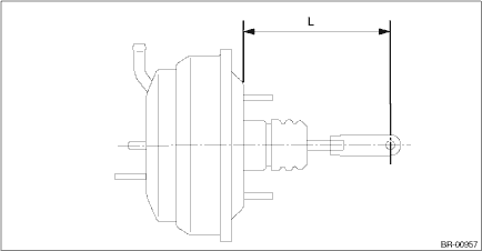
1. Check and adjust the operating rod of the vacuum booster assembly.
(1) Measure the length between the vacuum booster assembly mounting surface and clevis pin hole.
(2) If it is not within the specification, loosen the lock nut, rotate the vacuum booster assembly operating rod to adjust the rod length.
Specification L:
136.3 mm (5.37 in)
2. Install each part in the reverse order of removal.
CAUTION:
• Apply grease to the snap pin to prevent the operating rod from wear.
• Replace the clevis pin with new parts, and apply thin coat of NIGTIGHT LYW No. 2 grease to the clevis pin.
• When installing the master cylinder assembly, replace the seal sub assembly with a new part, and install it to the vacuum booster assembly.
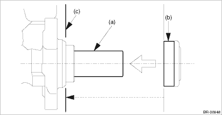
(a) | Primary piston | (b) | Seal sub ASSY | (c) | Install the seal sub ASSY to this surface. |
Tightening torque:
Vacuum booster assembly: 18 N·m (1.84 kgf-m, 13.3 ft-lb)
Master cylinder assembly: 13 N·m (1.33 kgf-m, 9.6 ft-lb)
Brake pipe flare nut: 19 N·m (1.94 kgf-m, 14.0 ft-lb)
Operating lock nut: 22 N·m (2.24 kgf-m, 16.2 ft-lb)
Knee airbag module: 7.5 N·m (0.76 kgf-m, 5.5 ft-lb)
3. Install the air conditioner pipe. General Description > COMPONENT">
4. Charge refrigerant. Refrigerant Charging Procedure > PROCEDURE">
5. Bleed air from the brake system. Air Bleeding > PROCEDURE">
6. Perform a road test to make sure the brakes do not drag.
 Removal
BRAKE > Brake BoosterREMOVALCAUTION:• Do not allow brake fluid to come in contact with the painted surface of the vehicle body. If it does, wash off with water and wipe away completely.• ...
 Brake fluid
...
Other materials:
Removal
SECURITY AND LOCKS > ReceiverREMOVALNOTE:Except for model with keyless entry1. Disconnect the ground cable from battery. NOTE">2. Remove the trim panel - rear apron LH. Rear Quarter Trim > REMOVAL">3. Remove the receiver assembly.(1) Disconnect the connector.(2) Remove the bo ...
Removal
EXTERIOR/INTERIOR TRIM > Side GarnishREMOVAL1. Remove the clips and detach the side garnish assembly.(1)Garnish ASSY - fender(2)Garnish ASSY - rear quarter(3)Garnish ASSY - side sill2. Remove the garnish assembly or protector on the fender panel.CAUTION:Do not reuse the garnish assembly and prote ...
Installation
EXTERIOR BODY PANELS > Front HoodINSTALLATIONCAUTION:The hood COMPL - front is heavy. When removing or installing the hinge COMPL - front hood, be sure to work in a group of two or more.1. To install the insulator - front hood and the seal - front duct, follow the removal procedure in the reverse ...
