Subaru Crosstrek Service Manual: Inspection
FUEL INJECTION (FUEL SYSTEMS)(H4DO) > Throttle Body
INSPECTION
1. THROTTLE SENSOR (METHOD WITH CIRCUIT TESTER)
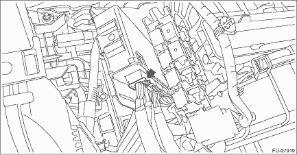
1. Remove the glove box. Glove Box > REMOVAL">
2. Turn the ignition switch to ON. (engine OFF)
3. Measure the voltage between ECM connector terminals.
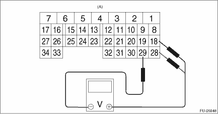
(A) | To ECM connector |
Throttle sensor | Accelerator pedal | Terminal No. | Standard |
Main | Not depressed (full closed) | 18 (+) and 29 (−) | Approx. 0.6 V |
Depressed (full opened) | Approx. 4.0 V | ||
Sub | Not depressed (full closed) | 28 (+) and 29 (−) | Approx. 1.5 V |
Depressed (full opened) | Approx. 4.2 V |
4. After inspection, install the related parts in the reverse order of removal.
2. THROTTLE SENSOR (METHOD WITH SUBARU SELECT MONITOR)
1. Turn the ignition switch to ON. (engine OFF)
2. Read the throttle opening angle signal and voltage of throttle sensor using Subaru Select Monitor. Subaru Select Monitor > OPERATION">
Throttle sensor | Throttle opening angle signal | Standard |
Main | 0.0% | Approx. 0.6 V |
100.0% | Approx. 4.0 V | |
Sub | 0.0% | Approx. 1.5 V |
100.0% | Approx. 4.2 V |
3. OTHER INSPECTIONS
1. Check that the throttle body has no deformation, cracks or other damages.
2. Check that the preheater hose has no cracks, damage or loose part.
 Throttle body
...
 Removal
FUEL INJECTION (FUEL SYSTEMS)(H4DO) > Throttle BodyREMOVAL1. Disconnect the ground cable from battery.2. Lift up the vehicle.3. Remove the under cover. Front Under Cover > REMOVAL">4. D ...
Other materials:
Inspection
COOLING(H4DO) > RadiatorINSPECTION1. Check that the radiator does not have deformation, cracks or damage.2. Check that the hose has no cracks, damage or loose part.3. Remove the radiator cap, fill the radiator with engine coolant, and then install the radiator cap tester to the filler neck of rad ...
Removal
FUEL INJECTION (FUEL SYSTEMS)(H4DO) > Oil Control SolenoidREMOVALCAUTION:If the engine oil is spilt over exhaust pipe or the under cover, wipe it off with cloth to avoid emission of smoke or causing a fire.1. INTAKE SIDE1. Disconnect the ground cable from battery.2. Remove the air intake duct. (R ...
Dtc p0101 mass or volume air flow sensor "a" circuit range/performance
ENGINE (DIAGNOSTICS)(H4DO) > Diagnostic Procedure with Diagnostic Trouble Code (DTC)DTC P0101 MASS OR VOLUME AIR FLOW SENSOR "A" CIRCUIT RANGE/PERFORMANCEDTC DETECTING CONDITION:Detected when two consecutive driving cycles with fault occur.TROUBLE SYMPTOM:• Improper idling• ...
