Subaru Crosstrek Service Manual: Ignition control system
ENGINE (DIAGNOSTICS)(H4DO) > Diagnostics for Engine Starting Failure
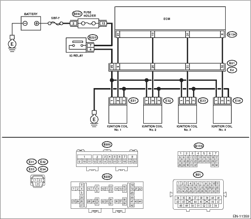
IGNITION CONTROL SYSTEM
CAUTION:
After servicing or replacing faulty parts, perform Clear Memory Mode Clear Memory Mode"> , and Inspection Mode Inspection Mode">.
Wiring diagram:
Engine electrical system Engine Electrical System">
| STEP | CHECK | YES | NO |
1.CHECK SPARK PLUG CONDITION.
1) Remove the spark plug. Spark Plug > REMOVAL">
2) Check the spark plug condition. Spark Plug > INSPECTION">
Is the check result OK?
Diagnostics for Engine Starting Failure > IGNITION CONTROL SYSTEM">Go to Step 2.
Replace the spark plug. Spark Plug">
2.CHECK IGNITION SYSTEM FOR SPARKS.
1) Connect the spark plug to ignition coil.
2) Release the fuel pressure. Fuel > PROCEDURE">
3) Contact the spark plug thread portion to engine.
4) While opening the throttle valve fully, crank the engine to check that spark occurs at each cylinder.
Does spark occur at each cylinder?
Check fuel pump system. Diagnostics for Engine Starting Failure > FUEL PUMP CIRCUIT">
Diagnostics for Engine Starting Failure > IGNITION CONTROL SYSTEM">Go to Step 3.
3.CHECK IGNITION COIL POWER SUPPLY CIRCUIT.
1) Turn the ignition switch to OFF.
2) Disconnect the connector from ignition coil.
3) Turn the ignition switch to ON.
4) Measure the voltage between ignition coil connector and engine ground.
Connector & terminal
(E31) No. 1 (+) — Engine ground (−):
(E32) No. 1 (+) — Engine ground (−):
(E33) No. 1 (+) — Engine ground (−):
(E34) No. 1 (+) — Engine ground (−):
Is the voltage 10 V or more?
Diagnostics for Engine Starting Failure > IGNITION CONTROL SYSTEM">Go to Step 4.
Repair the harness and connector.
NOTE:
In this case, repair the following item:
• Open or short to ground in harness of power supply circuit
• Poor contact of coupling connector
• Blown out of fuse
4.CHECK HARNESS OF IGNITION COIL GROUND CIRCUIT.
1) Turn the ignition switch to OFF.
2) Measure the resistance of harness between ignition coil connector and engine ground.
Connector & terminal
(E31) No. 3 — Engine ground:
(E32) No. 3 — Engine ground:
(E33) No. 3 — Engine ground:
(E34) No. 3 — Engine ground:
Is the resistance less than 5 ??
Diagnostics for Engine Starting Failure > IGNITION CONTROL SYSTEM">Go to Step 5.
Repair the open circuit in harness between ignition coil connector and engine grounding terminal.
5.CHECK HARNESS BETWEEN ECM AND IGNITION COIL CONNECTOR.
1) Disconnect the connector from ECM.
2) Measure the resistance of harness between ECM connector and ignition coil connector.
Connector & terminal
(B134) No. 21 — (E31) No. 2:
(B134) No. 10 — (E32) No. 2:
(B134) No. 31 — (E33) No. 2:
(B134) No. 8 — (E34) No. 2:
Is the resistance less than 1 ??
Diagnostics for Engine Starting Failure > IGNITION CONTROL SYSTEM">Go to Step 6.
Repair the harness and connector.
NOTE:
In this case, repair the following item:
• Open circuit of harness between ECM connector and the ignition coil connector
• Poor contact of coupling connector
6.CHECK HARNESS BETWEEN ECM AND IGNITION COIL CONNECTOR.
Measure the resistance of harness between ECM connector and engine ground.
Connector & terminal:
(B134) No. 21 — Engine ground:
(B134) No. 10 — Engine ground:
(B134) No. 31 — Engine ground:
(B134) No. 8 — Engine ground:
Is the resistance 1 M? or more?
Diagnostics for Engine Starting Failure > IGNITION CONTROL SYSTEM">Go to Step 7.
Repair the ground short circuit of harness between ECM connector and ignition coil connector.
7.CHECK FOR POOR CONTACT.
Check for poor contact of ECM connector.
Is there poor contact of ECM connector?
Repair the poor contact of ECM connector.
Replace the ignition coil. Ignition Coil">
 Procedure
ENGINE (DIAGNOSTICS)(H4DO) > Diagnostics for Engine Starting FailurePROCEDURE1. Check of the fuel amount↓2. Inspection of starter motor circuit Diagnostics for Engine Starting Failure > ST ...
 Fuel pump circuit
ENGINE (DIAGNOSTICS)(H4DO) > Diagnostics for Engine Starting FailureFUEL PUMP CIRCUITCAUTION:After servicing or replacing faulty parts, perform Clear Memory Mode Clear Memory Mode > OPERATION&q ...
Other materials:
Tire
SPECIFICATIONS > CrosstrekTIREModel2.0 L DOHC non-turboWheel size17 ? 7JTire sizeP225/55R17 95H225/55R17 97VTypeTubeless, steel belted radial ...
Dtc u0122 lost communication with vehicle dynamics control module
Blind Spot Detection/Rear Cross Traffic Alert (DIAGNOSTICS) > Diagnostic Procedure with Diagnostic Trouble Code (DTC)DTC U0122 LOST COMMUNICATION WITH VEHICLE DYNAMICS CONTROL MODULEDetected when CAN data from VDC CM does not arrive.NOTE:Perform the diagnosis for LAN system. Basic Diagnostic Pro ...
Removal
COOLING(H4DO) > Radiator Main Fan and Fan MotorREMOVAL1. Disconnect the ground cable from battery. NOTE">2. Remove the reservoir tank. Reservoir Tank > REMOVAL">3. Disconnect the connector from the main fan motor assembly.4. Remove the bolts which hold the radiator main fan s ...
