Subaru Crosstrek Service Manual: Fuel pressure Inspection
MECHANICAL(H4DO) > Fuel Pressure
INSPECTION
1. Release the fuel pressure. Fuel > PROCEDURE">
2. Open the fuel filler lid and remove the fuel filler cap.
NOTE:
This operation is required to release the inner pressure of the fuel tank.
3. Disconnect the fuel delivery tube from the fuel delivery pipe, and connect the fuel pressure gauge.
CAUTION:
• Be careful not to spill fuel.
• Catch the fuel from the tubes using a container or cloth.
(1) Disconnect the quick connector on the fuel delivery tube from the fuel pipe assembly, and remove the clip (A) securing the fuel delivery tube to the fuel pipe assembly.
NOTE:
Disconnect the quick connector as shown in the figure.
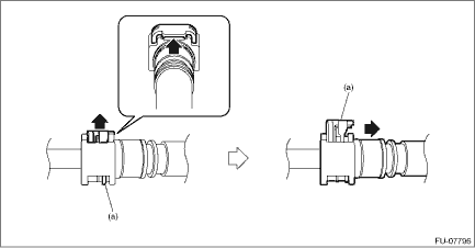
(a) | Slider |
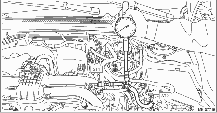
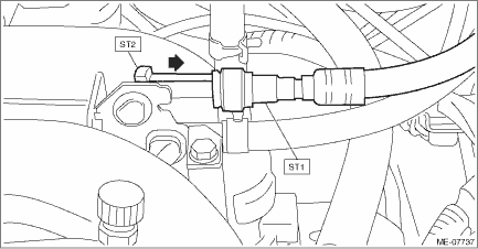
(2) Connect the fuel pressure gauge with ST1 and ST2.
CAUTION:
• Check that there is no damage or dust on the quick connector. If necessary, clean the seal surface of the pipe.
• When connecting the quick connector with slider, make sure to insert it all the way in before locking the slider.
• When it is difficult to lock the slider, check that the connector is fully inserted.
• After locking the slider, check that the quick connector is securely connected.
NOTE:
• ST1 is a SUBARU genuine part.
• When connecting the ST2 to the quick connector on the fuel delivery tube, connect as shown in the figure.
(a) | Slider |
| ST1 42075AG690 | FUEL HOSE |
| ST2 18471AA000 | FUEL PIPE ADAPTER |
4. Start the engine.
5. Check the fuel pressure after warming up the engine.
NOTE:
• The fuel pressure gauge registers 10 to 20 kPa (0.1 to 0.2 kg/cm2, 1 to 3 psi) higher than standard values during high-altitude operations.
• Check or replace the fuel pump and fuel delivery line if the fuel pressure is out of the standard.
Fuel pressure:
Standard
340 — 400 kPa (3.5 — 4.1 kg/cm2, 49 — 58 psi)
6. After inspection, install the related parts in the reverse order of removal.
CAUTION:
• Before removing the fuel pressure gauge, release the fuel pressure.
• Be careful not to spill fuel.
• Catch the fuel from hoses and tubes using a container or cloth.
• Check that there is no damage or dust on the quick connector. If necessary, clean the seal surface of the pipe.
• When connecting the quick connector with slider, make sure to insert it all the way in before locking the slider.
• When it is difficult to lock the slider, check that the connector is fully inserted.
• After locking the slider, check that the quick connector is securely connected.
NOTE:
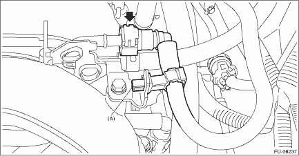
• When disconnecting the ST1, install the ST2 to the fuel pipe assembly, and press the ST2 in the direction of arrow to disconnect the quick connector on the ST1.
| ST1 42075AG690 | FUEL HOSE |
| ST2 42099AE000 | QUICK CONNECTOR RELEASE |
• Disconnect the quick connector on the fuel delivery tube as shown in the figure.
(a) | Slider |
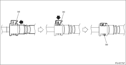
• Connect the quick connector on the fuel delivery tube as shown in the figure.
(a) | Slider |
 Engine trouble in general Inspection
MECHANICAL(H4DO) > Engine Trouble in GeneralINSPECTIONNOTE:The “RANK” shown in the chart shows the possibilities of the cause of trouble in order from “Very often” to &ldquo ...
 Idle speed Inspection
MECHANICAL(H4DO) > Idle SpeedINSPECTION1. Before checking the idle speed, check the following item:(1) Check the air cleaner element is free from clogging, ignition timing is correct, spark plugs a ...
Other materials:
Electrical specification
VEHICLE DYNAMICS CONTROL (VDC) (DIAGNOSTICS) > Control Module I/O SignalELECTRICAL SPECIFICATION• Models without EyeSightNOTE:• Terminal numbers in VDCCM&H/U connector (on the control module side) are shown in the figure.• When the connector is removed from the VDCCM&H/U ...
System features
BSD/RCTA consists of the following functions.
To detect a vehicle in a blind spot on an
adjacent lane or a vehicle approaching at
high speed while driving the vehicle (Blind
Spot Detection)
To detect a vehicle approaching from
the right or left while reversing the vehicle
(Rear Cross ...
Vehicle load limit - how to determine
The load-carrying capability of your Subaru Ascent is defined by weight limitations
rather than available interior or cargo space. The maximum permissible load is clearly
indicated on the vehicle placard located on the driver’s side door pillar. On this
label, you will find the statement: &q ...
