Subaru Crosstrek Service Manual: Engine control module (ecm) i/o signal Electrical specification
ENGINE (DIAGNOSTICS)(H4DO) > Engine Control Module (ECM) I/O Signal
ELECTRICAL SPECIFICATION
1. ENGINE CONTROL MODULE (ECM)
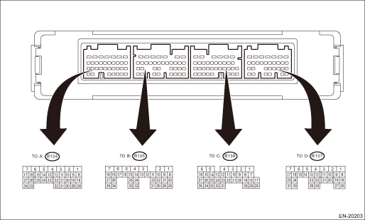
Description | Connector No. | Terminal No. | Signal (V) | Note | ||
Ignition SW ON (Engine OFF) | Engine ON (Idling) | |||||
Crankshaft position sensor | (+) signal | B136 | 16 | 5 | 0 or 5 | Waveform* |
(−) signal | B136 | 27 | 0 | 0 | — | |
Front oxygen (A/F) sensor | (+) signal | B136 | 19 | 2.8 — 3.2 | 2.8 — 3.2 | — |
(−) signal | B136 | 18 | 2.4 — 2.7 | 2.4 — 2.7 | — | |
Rear oxygen sensor | Signal | B136 | 21 | 0 | 0 — 0.9 | — |
Front oxygen (A/F) sensor heater signal | B136 | 5 | Battery voltage | 0 or battery voltage | Waveform | |
Rear oxygen sensor heater signal | B134 | 6 | Battery voltage | 0 or battery voltage | Waveform | |
Oxygen sensor | Shield | B136 | 30 | 0 | 0 | — |
Engine coolant temperature sensor | Signal | B134 | 30 | 1 — 1.4 | 1 — 1.6 | — |
Air flow sensor | Signal | B137 | 22 | — | 0.3 — 4.5 | — |
Shield | B137 | 28 | 0 | 0 | — | |
Ground | B137 | 29 | 0 | 0 | — | |
Intake air temperature sensor signal | B137 | 12 | 0.3 — 4.6 | 0.3 — 4.6 | — | |
Engine oil temperature sensor signal | B134 | 20 | 1 — 1.4 | 1 — 1.6 | — | |
Starter switch | B137 | 17 | Waveform | Waveform | Model without push button start: Waveform Models with push button start: Waveform | |
Accessory cut request | B135 | 32 | Waveform | Waveform | Model without push button start: Waveform Models with push button start: Waveform | |
Starter switch 2 | B137 | 14 | Waveform | Waveform | Model without push button start: Waveform Models with push button start: Waveform | |
Starter cut relay | B135 | 34 | Waveform | Waveform | Model without push button start: Waveform Models with push button start: Waveform | |
Ignition switch | B137 | 27 | Battery voltage | Battery voltage | — | |
Neutral position switch | B137 | 16 | ON: 0 OFF: Battery voltage | ON: 0 OFF: Battery voltage | — | |
Delivery mode switch | B137 | 13 | Battery voltage | Battery voltage | When fuse is installed: 0 | |
Knock sensor | Signal | B136 | 28 | 2.5 | 2.5 | — |
Shield | B136 | 29 | 0 | 0 | — | |
Back-up power supply | B137 | 2 | Battery voltage | Battery voltage | — | |
Control module power supply | B136 | 6 | Battery voltage | Battery voltage | — | |
B137 | 1 | Battery voltage | Battery voltage | — | ||
Sensor power supply | B134 | 19 | 5 | 5 | — | |
B135 | 22 | 5 | 5 | — | ||
Ignition control | #1 | B134 | 21 | 0 | 0 or 5 | Waveform |
#2 | B134 | 10 | 0 | 0 or 5 | Waveform | |
#3 | B134 | 31 | 0 | 0 or 5 | Waveform | |
#4 | B134 | 8 | 0 | 0 or 5 | Waveform | |
Fuel injector | #1 | B134 | 12 | Battery voltage | 0 or battery voltage | Waveform |
#2 | B134 | 22 | Battery voltage | 0 or battery voltage | Waveform | |
#3 | B134 | 32 | Battery voltage | 0 or battery voltage | Waveform | |
#4 | B134 | 13 | Battery voltage | 0 or battery voltage | Waveform | |
Fuel pump relay control | B135 | 19 | Battery voltage | ON: 0.5 or less OFF: Battery voltage | — | |
A/C relay control | B135 | 35 | ON: 0.5 or less OFF: Battery voltage | ON: 0.5 or less OFF: Battery voltage | — | |
A/C switch | B137 | 26 | ON: Battery voltage OFF: 0 | ON: Battery voltage OFF: 0 | Manual A/C model | |
Blower fan switch | B137 | 20 | ON: 0 OFF: Battery voltage | ON: 0 OFF: Battery voltage | Manual A/C model | |
A/C middle pressure switch | B137 | 8 | ON: 0 OFF: Battery voltage | ON: 0 OFF: Battery voltage | — | |
Main fan relay control | B135 | 12 | ON: 0.5 or less OFF: Battery voltage | ON: 0.5 or less OFF: Battery voltage | — | |
Sub fan relay control | B135 | 11 | ON: 0.5 or less OFF: Battery voltage | ON: 0.5 or less OFF: Battery voltage | — | |
Engine speed output | B135 | 15 | — | 0 or battery voltage | Waveform | |
Purge control solenoid valve | B134 | 11 | Battery voltage | Battery voltage | When in operation: 0 or battery voltage | |
EGR control valve | Signal 1 | B136 | 11 | Battery voltage | 0 or battery voltage | — |
Signal 2 | B136 | 13 | Battery voltage | 0 or battery voltage | — | |
Signal 3 | B136 | 31 | Battery voltage | 0 or battery voltage | — | |
Signal 4 | B136 | 32 | Battery voltage | 0 or battery voltage | — | |
Manifold absolute pressure sensor signal | B136 | 20 | 3.4 — 3.8 | 1 — 1.6 | — | |
Electronic throttle control | Main signal | B134 | 18 | Approx. 0.7 | Approx. 0.6 — 0.7 | Fully closed: Approx. 0.6 Fully open: Approx. 4.0 |
Sub signal | B134 | 28 | Approx. 1.6 | Approx. 1.5 — 1.6 | Fully closed: Approx. 1.5 Fully open: Approx. 4.2 | |
Electronic throttle control motor (+) | B134 | 2 | Duty waveform | Duty waveform | Drive frequency: 500 Hz | |
Electronic throttle control motor (−) | B134 | 1 | Duty waveform | Duty waveform | Drive frequency: 500 Hz | |
Electronic throttle control motor power supply | B135 | 7 | Battery voltage | Battery voltage | — | |
Electronic throttle control motor relay | B135 | 17 | 0 | 0 | — | |
Intake oil control solenoid RH | B134 | 17 | Battery voltage | 0 or battery voltage | Waveform | |
Intake oil control solenoid LH | B134 | 16 | Battery voltage | 0 or battery voltage | Waveform | |
Exhaust oil control solenoid RH | B134 | 7 | Battery voltage | 0 or battery voltage | Waveform | |
Exhaust oil control solenoid LH | B134 | 5 | Battery voltage | 0 or battery voltage | Waveform | |
Intake camshaft position sensor RH | B136 | 26 | 0 or 5 | 0 or 5 | Waveform* | |
Intake camshaft position sensor LH | B136 | 15 | 0 or 5 | 0 or 5 | Waveform* | |
Exhaust camshaft position sensor RH | B136 | 14 | 0 or 5 | 0 or 5 | Waveform* | |
Exhaust camshaft position sensor LH | B136 | 25 | 0 or 5 | 0 or 5 | Waveform* | |
Camshaft position sensor ground | B136 | 34 | 0 | 0 | — | |
Accelerator pedal position sensor | Main signal | B135 | 23 | Fully closed: 0.4 — 1 Fully opened: 2.4 — 3.7 | Fully closed: 0.4 — 1 Fully opened: 2.4 — 3.7 | — |
Main power supply | B135 | 21 | 5 | 5 | — | |
Ground (main) | B135 | 29 | 0 | 0 | — | |
Sub signal | B135 | 31 | Fully closed: 0.3 — 1.1 Fully opened: 2.3 — 3.8 | Fully closed: 0.3 — 1.1 Fully opened: 2.3 — 3.8 | — | |
Starter relay | B135 | 26 | Waveform | Waveform | Model without push button start: Waveform Models with push button start: Waveform | |
Clutch switch | B137 | 15 | ON: 0 OFF: Battery voltage | ON: 0 OFF: Battery voltage | — | |
Brake switch 1 (Brake switch) | B137 | 7 | When brake pedal is depressed: 0 When brake pedal is released: Battery voltage | When brake pedal is depressed: 0 When brake pedal is released: Battery voltage | — | |
Brake switch 2 (Stop light switch) | B137 | 3 | When brake pedal is depressed: Battery voltage When brake pedal is released: 0 | When brake pedal is depressed: Battery voltage When brake pedal is released: 0 | — | |
Cruise control command switch | B137 | 30 | When operating nothing: 3.5 — 4.5 When operating RES/ACC: 2.5 — 3.5 When operating SET/COAST: 0.5 — 1.5 When operating CANCEL: 0 — 0.5 | When operating nothing: 3.5 — 4.5 When operating RES/ACC: 2.5 — 3.5 When operating SET/COAST: 0.5 — 1.5 When operating CANCEL: 0 — 0.5 | — | |
Cruise control main switch | B137 | 23 | ON: 0 OFF: 5 | ON: 0 OFF: 5 | — | |
CAN communication (MAIN-CAN) | (Hi) | B137 | 19 | — | — | — |
(Lo) | B137 | 18 | — | — | — | |
Self-shutoff control | B135 | 13 | 0 | 0 | ||
 Electrical component location Location
ENGINE (DIAGNOSTICS)(H4DO) > Electrical Component LocationLOCATION1. CONTROL MODULE(1)Engine control module (ECM)(3)Malfunction indicator light(4)Data link connector(2)Delivery (test) mode fuse ...
 General diagnostic table Inspection
ENGINE (DIAGNOSTICS)(H4DO) > General Diagnostic TableINSPECTION1. ENGINENOTE:Malfunction of parts other than those listed is also possible. Engine Trouble in General">SymptomsFaulty parts1 ...
Other materials:
Dtc b28a3 eyesight communication(meter)
EyeSight (DIAGNOSTICS) > Diagnostic Procedure with Diagnostic Trouble Code (DTC)DTC B28A3 EyeSight COMMUNICATION(METER)Detected when the combination meter detects the malfunction of stereo camera.DTC DETECTING CONDITION:• Defective CAN system• Defective combination meter• Defect ...
16
CRUISE CONTROL SYSTEM (DIAGNOSTICS) > Diagnostic Procedure with Cancel Code16Detected when ignition switch is turned to OFF or malfunction related to the ignition switch occurs.TROUBLE SYMPTOM:Cruise control cannot be set.WIRING DIAGRAM:Cruise control system Cruise Control System > WIRING DIA ...
Key lock-in prevention function
The Subaru Ascent is equipped with a key lock-in prevention system designed to
prevent accidental locking of the keys inside the vehicle.
Under the following conditions, the Subaru Ascent doors will not lock when the
door lock switch is pressed while a front door remains open:
The key is st ...
