Subaru Crosstrek Service Manual: Electrical component location Location
ENGINE (DIAGNOSTICS)(H4DO) > Electrical Component Location
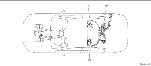
LOCATION
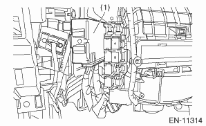
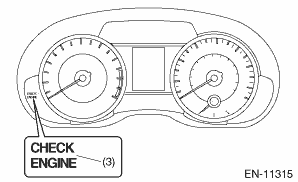
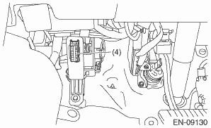
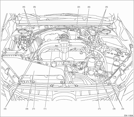
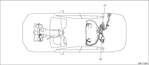
1. CONTROL MODULE
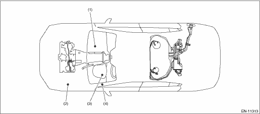
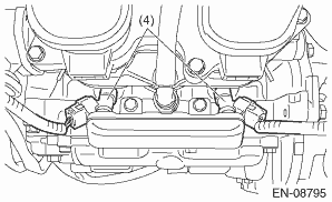
(1) | Engine control module (ECM) | (3) | Malfunction indicator light | (4) | Data link connector |
(2) | Delivery (test) mode fuse |

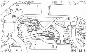
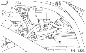
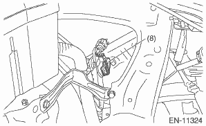
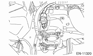
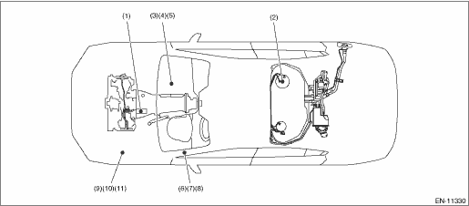
2. SENSOR
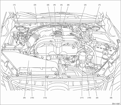
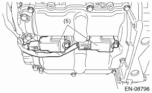
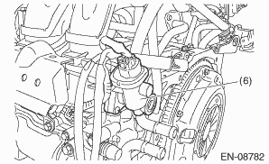
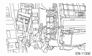
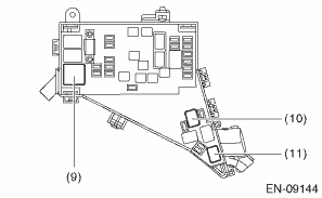
(1) | Mass air flow and intake air temperature sensor | (5) | Crankshaft position sensor | (9) | Intake camshaft position sensor |
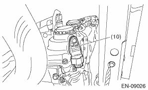
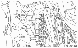
(2) | Tumble generator valve actuators (with built-in opening angle switch) | (6) | Knock sensor | (10) | Exhaust camshaft position sensor |
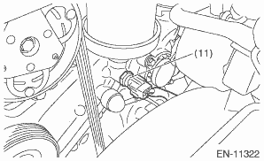
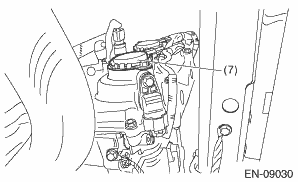
(3) | Electronic throttle control | (7) | Battery current sensor | (11) | Engine oil temperature sensor |
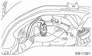
(4) | Manifold absolute pressure sensor | (8) | Battery temperature sensor | (12) | Engine coolant temperature sensor |
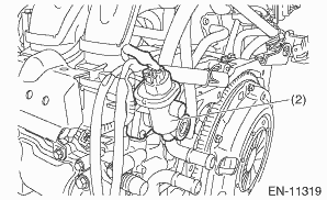
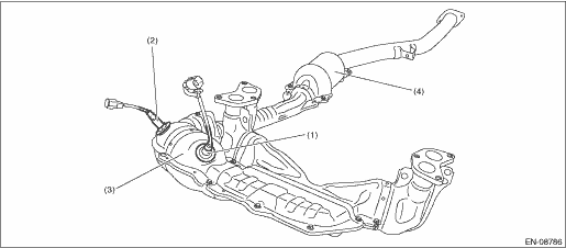
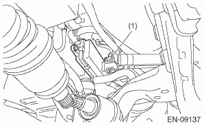
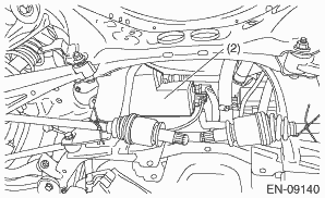
(1) | Front oxygen (A/F) sensor | (3) | Front catalytic converter | (4) | Rear catalytic converter |
(2) | Rear oxygen sensor |
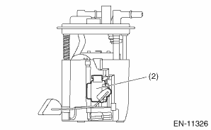
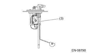
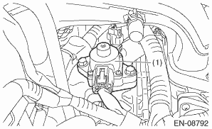
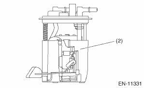
(1) | Leak check valve ASSY (with built-in pressure sensor) | (2) | Fuel level sensor | (3) | Fuel sub level sensor |

3. SOLENOID VALVE, ACTUATOR, EMISSION CONTROL SYSTEM PARTS AND IGNITION SYSTEM PARTS
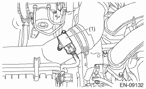
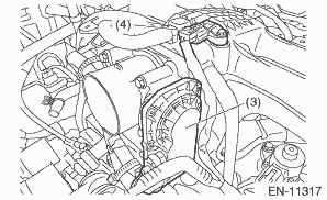
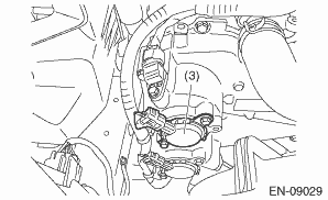
(1) | EGR control valve | (4) | Fuel injector | (6) | Tumble generator valve actuator |
(2) | Purge control solenoid valve | (5) | Ignition coil | (7) | Exhaust oil control solenoid |
(3) | Intake oil control solenoid |
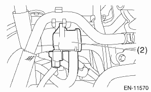
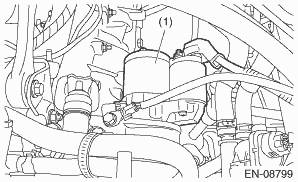
(1) | Leak check valve ASSY | (2) | Canister |
(1) | Starter | (5) | Fuel pump relay | (9) | Radiator main fan relay 1 |
(2) | Fuel pump | (6) | A/F, oxygen sensor relay | (10) | Radiator main fan relay 2 |
(3) | Main relay | (7) | Electronic throttle control relay | (11) | Radiator sub fan relay |
(4) | IG relay | (8) | Starter relay 1 |
 Drive cycle Procedure
ENGINE (DIAGNOSTICS)(H4DO) > Drive CyclePROCEDUREIt is necessary to perform the drive cycle listed below if DTC is not found in the Inspection Mode. It is possible to complete diagnosis of the DTC ...
 Engine control module (ecm) i/o signal Electrical specification
ENGINE (DIAGNOSTICS)(H4DO) > Engine Control Module (ECM) I/O SignalELECTRICAL SPECIFICATION1. ENGINE CONTROL MODULE (ECM)DescriptionConnector No.Terminal No.Signal (V)NoteIgnition SW ON(Engine OFF) ...
Other materials:
Suspension
SPECIFICATIONS > CrosstrekSUSPENSIONModel2.0 L DOHC non-turboFrontMacpherson strut type suspensionRearDouble-wishbone type suspension ...
Dtc p0962 pressure control solenoid "a" control circuit low
CONTINUOUSLY VARIABLE TRANSMISSION (DIAGNOSTICS) > Diagnostic Procedure with Diagnostic Trouble Code (DTC)DTC P0962 PRESSURE CONTROL SOLENOID "A" CONTROL CIRCUIT LOWDTC detecting condition:Immediately at fault recognitionTrouble symptom:• Engine speed increases abruptly, and can n ...
Basic information before use
WARNING
When the vehicle is stopped with the
engine running, always apply the
parking brake for safety. Failure to
do so may result in loss of control of
your vehicle and cause an accident
or serious injury.
CAUTION
To prevent damaging the screen,
touch the screen keys with your
finge ...
