Subaru Crosstrek Service Manual: Electrical specification
POWER ASSISTED SYSTEM (POWER STEERING) (DIAGNOSTICS) > Control Module I/O Signal
ELECTRICAL SPECIFICATION
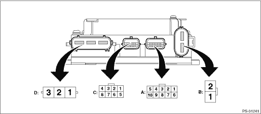
NOTE:
The terminal numbers of the power steering control module connectors are as indicated in the figure.
Contents | Terminal No. | Input/output signal |
Measured value and measuring conditions | ||
Power supply (IG SW) | A1 | Battery voltage is detected with the ignition switch ON when measuring between A1 — B1. |
Subaru Select Monitor communication line | A2 | Digital signal; can not be measured |
Shield GND | A3 | 0 V is constantly detected. |
Main torque sensor | A4 | The voltage changes when the steering is operated to the right or left with the ignition switch ON. |
Sub torque sensor | A5 | The voltage changes when the steering is operated to the right or left with the ignition switch ON. |
CAN communication | A6 | Digital signal; can not be measured |
CAN communication | A7 | Digital signal; can not be measured |
Torque sensor operating power supply | A8 | Approximately 8 V is detected with ignition switch ON. |
Torque sensor ground | A9 | 0 V is constantly detected. |
Torque sensor standard power supply | A10 | Approximately 3 V is detected with ignition switch ON. |
Ground | B1 | Battery voltage is constantly detected when measuring between B1 — B2. |
Power supply | B2 | |
Resolver S1 | C1 | Varies depending on the operational status of the motor. |
Resolver S3 | C2 | |
Resolver S2 | C3 | |
Resolver S4 | C4 | |
Excitation power supply for resolver | C5 | |
Common output | C6 | |
Motor U phase | D1 | Varies depending on the motor output. |
Motor V phase | D2 | |
Motor W phase | D3 |

 Wiring diagram
POWER ASSISTED SYSTEM (POWER STEERING) (DIAGNOSTICS) > Control Module I/O SignalWIRING DIAGRAM(1)Battery(5)Engine control module (ECM)(9)Torque sensor (main & sub)(2)Ignition switch(6)Power ste ...
Other materials:
List
HVAC SYSTEM (AUTO A/C) (DIAGNOSTICS) > Read Current DataLISTItems to be displayedUnit of measureContentsNoteIn-vehicle Sensor Temperature°C (°F)A/C control panel input value — Quantity of SunloadW/m2A/C control panel input value — Air conditioner pressure SWON/OFFA/C con ...
Locking and unlocking from the inside
How to use the lock lever
Move the lock lever rearward to unlock the door.
Move the lock lever forward to lock the door.
Before driving your Subaru Ascent, always ensure that all doors and the rear
gate are securely closed.
A visible red indicator appears on the lock lever when the d ...
Roof antenna (for Rod type)
CAUTION
Be sure to remove the antenna
rod before entering garages,
parking towers and other locations
with low ceilings.
Remove the antenna rod before
washing your car at a car wash. If
the antenna rod is left attached, it
may scratch the roof.
When reinstalling the removed
ant ...
