Subaru Crosstrek Service Manual: Electrical specification
KEYLESS ACCESS WITH PUSH BUTTON START SYSTEM (DIAGNOSTICS) > Control Module I/O Signal
ELECTRICAL SPECIFICATION
1. KEYLESS ACCESS CM
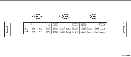
Terminal No. | Terminal symbol | Content |
(B572) No. 2 | +B | +B |
(B572) No. 3 | INDS | Start switch indicator (green) output |
(B572) No. 5 | N-SW | Neutral switch input |
(B572) No. 7 | STSW | STSW output |
(B572) No. 9 | IG2D | IG2 relay drive output |
(B572) No. 10 | CLUT | Clutch switch input |
(B572) No. 11 | GND | GND |
(B572) No. 13 | EGIO | Immobilizer communication 1 |
(B572) No. 17 | TACH | Engine speed input |
(B572) No. 18 | STPI | Stop light switch input |
(B573) No. 1 | CG8B | Outside rear antenna output − |
(B573) No. 2 | CLG8 | Outside rear antenna output + |
(B573) No. 5 | RCO | Tuner power supply |
(B573) No. 8 | CG7B | Inside rear antenna output − |
(B573) No. 9 | CLG7 | Inside rear antenna output + |
(B573) No. 15 | IDW | ID code box presence judgment terminal |
(B573) No. 17 | RDA | Tuner reception data input |
(B573) No. 19 | RSSI | Tuner reception start signal input |
(B573) No. 27 | TSW5 | Rear gate lock request SW input / trunk opener button input |
(B573) No. 28 | ACCR | ACC cutoff input |
(B574) No. 1 | VC5 | Immobilizer amplifier power supply (start switch) |
(B574) No. 2 | CG5B | Inside front antenna output − |
(B574) No. 3 | CLG5 | Inside front antenna output + |
(B574) No. 4 | ACCD | ACC relay drive output |
(B574) No. 5 | IG | IGN power supply |
(B574) No. 6 | IG1D | IG1 relay drive output |
(B574) No. 7 | CODE | Immobilizer signal reception (start switch) |
(B574) No. 8 | TSW2 | Passenger’s lock sensor signal input |
(B574) No. 9 | TXCT | Immobilizer signal transmission (start switch) |
(B574) No. 10 | CG2B | Passenger’s antenna output − |
(B574) No. 11 | CLG2 | Passenger’s antenna output + |
(B574) No. 12 | CLG1 | Driver’s antenna output + |
(B574) No. 13 | CG1B | Driver’s antenna output − |
(B574) No. 14 | CANH | HS-CAN H |
(B574) No. 15 | CANL | HS-CAN L |
(B574) No. 16 | SWIL | Start switch character illumination output |
(B574) No. 17 | LIN | LIN communication |
(B574) No. 18 | INDW | Start switch indicator (orange) output |
(B574) No. 19 | POS1 | Driver’s sensor drive power supply |
(B574) No. 20 | TSW1 | Driver’s lock sensor signal input |
(B574) No. 21 | POS2 | Passenger’s sensor drive power supply |
(B574) No. 22 | SEN1 | Driver’s unlock sensor signal input |
(B574) No. 23 | SEN2 | Passenger’s unlock sensor signal input |
(B574) No. 24 | AGND | Immobilizer amplifier GND (start switch) |
(B574) No. 25 | P | Parking position switch input |
(B574) No. 26 | SLP | Steering lock position input |
(B574) No. 27 | SPD | Vehicle speed signal input |
(B574) No. 28 | SSW1 | Start switch input 1 |
(B574) No. 29 | SLR+ | Steering motor power supply signal output |
(B574) No. 30 | SSW2 | Start switch input 2 |
Disconnect the control module connector (B572) before checking the following items.
NOTE:
If the measured value is out of standard, it is possible that the vehicle has a fault.
Terminal No. | Item | Measuring condition | Standard |
(B572) No. 2 (+B) ←> (B572) No. 11 (GND) | Voltage | Always | 9.5 — 16 V |
(B572) No. 11 (GND) ←> Chassis ground | Resistance | Always | Less than 1 ? |
NOTE:
If the measured value is out of standard, it is possible that the vehicle has a fault.
Terminal No. | Item | Measuring condition | Standard |
(B573) No. 15 (IDW) ←> Chassis ground (For EK, ER, EN models only) | Continuity | Always | Continuity exists |
Disconnect the control module connectors (B574) and (B572) before checking the following items.
NOTE:
If the measured value is out of standard, it is possible that the vehicle has a fault.
Terminal No. | Item | Measuring condition | Standard |
(B574) No. 4 (ACCD) ←> Chassis ground | Resistance | Always (20°C) | 152.61 — 216.5 ? |
(B572) No. 9 (IG2D) ←> Chassis ground | Resistance | Always (20°C) | 74.15 — 460.88 ? |
(B574) No. 6 (IG1D) ←> Chassis ground | Resistance | Always (20°C) | 50.87 — 72.17 ? |
(B572) No. 18 (STP1) ←> Chassis ground (AT model only) | Voltage | Brake pedal depressed > released | 11 — 14 V > 1 V or less |
(B574) No. 25 (P) ←> Chassis ground (AT model only) | Resistance | Except for shift positions P > Shift position P | 40 k? or more > 200 ? or less |
(B574) No. 27 (SPD) ←> Chassis ground | Resistance | Always | 30 k? or more |
(B574) No. 28 (SSW1) ←> Chassis ground | Resistance | Push button ignition switch pressed > released | Less than 1 ? > 10 k? or more |
(B574) No. 29 (SLR+) ←> Chassis ground | Resistance | Always | 10 k? or more |
(B574) No. 30 (SSW2) ←> Chassis ground | Resistance | Push button ignition switch pressed > released | Less than 1 ? > 10 k? or more |
(B574) No. 17 (LIN) ←> Chassis ground | Continuity | Always | Continuity does not exist |
(B574) No. 14 (CANH) ←> Chassis ground | Pulse | ACC ON or IGN ON | Pulse generation |
(B574) No. 15 (CANL) ←> Chassis ground | Pulse | ACC ON or IGN ON | Pulse generation |
Connect the control module connector before checking the following items.
NOTE:
If the measured value is out of standard, it is possible that the keyless access CM has a fault.
Terminal No. | Item | Measuring condition | Standard |
(B574) No. 1 (VC5) ←> (B574) No. 24 (AGND) | Voltage | 30 seconds or more have passed after the door was opened or closed with IG OFF and the brake pedal released. | 1 V or less |
Waveform | Within 30 seconds after the push button ignition switch is pressed with IG OFF and access key not in the passenger room | Waveform 1 | |
(B574) No. 2 (CG5B) ←> (B572) No. 11 (GND) | Pulse | All doors closed, ACC and IG OFF, access key not in passenger room, touch sensor (lock) OFF > ON | No pulse output > Pulse output detected |
(B574) No. 3 (CLG5) ←> (B572) No. 11 (GND) | Pulse | All doors closed, ACC and IG OFF, access key not in passenger room, touch sensor (lock) OFF > ON | No pulse output > Pulse output detected |
(B574) No. 4 (ACCD) ←> (B572) No. 11 (GND) | Voltage | IG OFF > ACC ON | 1 V or less > 9 — 14 V |
(B574) No. 6 (IG1D) ←> (B572) No. 11 (GND) | Voltage | ACC ON > IG ON | 1 V or less > 9 — 14 V |
(B574) No. 7 (CODE) ←> (B574) No. 24 (AGND) | Voltage | 30 seconds or more have passed after the door was opened or closed with IG OFF and the brake pedal released. | 1 V or less |
Waveform | Turn the ignition switch to OFF and with the access key near the push button ignition switch, press the push button ignition switch*1 | Waveform 2 | |
(B574) No. 9 (TXCT) ←> (B574) No. 24 (AGND) | Voltage | 30 seconds or more have passed after the door was opened or closed with IG OFF and the brake pedal released. | 1 V or less |
Waveform | Turn the ignition switch to OFF and with the access key near the push button ignition switch, press the push button ignition switch*1 | Waveform 3 | |
(B574) No. 10 (CG2B) ←> (B572) No. 11 (GND) | Pulse | ACC and IG OFF, all doors closed, all doors locked by lock operation with wireless remote control, access key not in passenger room | No pulse output > Pulse output detected |
(B574) No. 11 (CLG2) ←> (B572) No. 11 (GND) | Pulse | ACC and IG OFF, all doors closed, all doors locked by lock operation with wireless remote control, access key not in passenger room | No pulse output > Pulse output detected |
(B574) No. 12 (CLG1) ←> (B572) No. 11 (GND) | Pulse | ACC and IG OFF, all doors closed, all doors locked by lock operation with wireless remote control, access key not in passenger room | No pulse output > Pulse output detected |
(B574) No. 13 (CG1B) ←> (B572) No. 11 (GND) | Pulse | ACC and IG OFF, all doors closed, all doors locked by lock operation with wireless remote control, access key not in passenger room | No pulse output > Pulse output detected |
(B574) No. 19 (POS1) ←> (B572) No. 11 (GND) | Voltage | ACC and IG OFF > ACC or IG ON | 9 — 14 V > less than 2 V |
(B574) No. 21 (POS2) ←> (B572) No. 11 (GND) | Voltage | ACC and IG OFF > ACC or IG ON | 9 — 14 V > less than 2 V |
(B574) No. 24 (AGND) ←> Chassis ground | Resistance | Always | Less than 1 ? |
(B574) No. 25 (P) ←> (B572) No. 11 (GND) (AT model only) | Voltage | Except for shift positions P > Shift position P | 9 — 14 V or more > 1.5 V or less |
(B574) No. 26 (SLP) ←> (B572) No. 11 (GND) | Voltage | With ignition switch OFF and shift position P, Steering lock > Steering unlock | 11 — 14 V > 1.2 V or less |
(B574) No. 27 (SPD) ←> Chassis ground | Pulse | Driving at approx. 5 km/h | Pulse generation according to vehicle speed (approx. 5 km/h: 3.54 Hz) |
(B574) No. 28 (SSW1) ←> (B572) No. 11 (GND) | Voltage | Push button ignition switch released > pressed | 11 — 14 V > 1 V or less |
(B574) No. 29 (SLR+) ←> (B572) No. 11 (GND) | Voltage | When the following conditions are met, the doors are closed > opened, and steering lock motor is driven |
• Steering lock is unlocked
• IG OFF
• Shift position P
11 — 14 V (Steering lock motor is stopped) > 1 V or less (Steering lock motor is driven)
(B574) No. 30 (SSW2) ←> (B572) No. 11 (GND)
Voltage
Push button ignition switch released > pressed
11 — 14 V > 1 V or less
(B573) No. 1 (CG8B) ←> (B572) No. 11 (GND)
Pulse
ACC and IG OFF, all doors closed, all doors locked, rear gate opener button OFF > ON
No pulse output > Pulse output detected
(B573) No. 2 (CLG8) ←> (B572) No. 11 (GND)
Pulse
ACC and IG OFF, all doors closed, all doors locked, rear gate opener button OFF > ON
No pulse output > Pulse output detected
(B573) No. 5 (RCO) ←> (B572) No. 11 (GND)
Voltage
ACC and IG OFF, access key is locked or unlock switch OFF > ON
1 V or less > 4.5 — 5.5 V
(B573) No. 8 (CG7B) ←> (B572) No. 11 (GND)
Pulse
All doors closed, ACC and IG OFF, access key not in passenger room, touch sensor (lock) OFF > ON
No pulse output > Pulse output detected
(B573) No. 9 (CLG7) ←> (B572) No. 11 (GND)
Pulse
All doors closed, ACC and IG OFF, access key not in passenger room, touch sensor (lock) OFF > ON
No pulse output > Pulse output detected
(B573) No. 19 (RSSI) ←> (B572) No. 11 (GND)
Voltage
All doors closed, all doors locked, access key is locked or unlock switch OFF > ON
11 — 14 V > 2 V or less
(B573) No. 27 (TSW5) ←> (B572) No. 11 (GND)
Pulse/voltage
ACC and IG OFF, all doors locked, rear gate lock button OFF > ON
9 V or more > less than 2 V
(B572) No. 9 (IG2D) ←> (B572) No. 11 (GND)
Voltage
ACC ON > IG ON
1 V or less > 9 — 14 V
(B572) No. 13 (EGIO) ←> (B574) No. 24 (AGND)
Voltage/pulse
Within 3 seconds after engine has been initially ignited or within 3 seconds after initial IG ON following battery removal and installation
11 to 14 V > pulse generation (waveform 4)
(B574) No. 8 (TSW2) ←> (B572) No. 11 (GND)
Voltage
ACC and IG OFF, all doors closed, all doors locked, access key carried, passenger’s seat touch sensor (lock) OFF > ON
9 V or more > less than 2 V (> 9 V or more)
(B574) No. 20 (TSW1) ←> (B572) No. 11 (GND)
Voltage
ACC and IG OFF, all doors closed, all doors locked, access key carried, driver’s seat touch sensor (lock) OFF > ON
9 V or more > less than 2 V (> 9 V or more)
(B574) No. 23 (SEN2) ←> (B572) No. 11 (GND)
Voltage
ACC and IG OFF, all doors closed, all doors locked, access key carried, passenger’s seat touch sensor (unlock) OFF > ON
9 V or more > less than 2 V (> 9 V or more)
(B574) No. 22 (SEN1) ←> (B572) No. 11 (GND)
Voltage
ACC and IG OFF, all doors closed, all doors locked, access key carried, driver’s seat touch sensor (unlock) OFF > ON
9 V or more > less than 2 V (> 9 V or more)
(B574) No. 16 (SWIL) ←> (B572) No. 11 (GND)
Voltage
When illumination of start switch goes off, headlight OFF > ON
Less than 2 V > 9 V or more
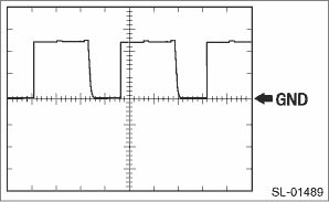
(B572) No. 17 (TACH) ←> Chassis ground
Waveform
While engine idling
Pulse generation (waveform 5)
(B573) No. 28 (ACCR) ←> (B572) No. 11 (GND)
Voltage
Brake pedal depressed, push button ignition switch pressed (while cranking) > Except when cranking
Less than 2 V > 9 V or more
(B572) No. 5 (N-SW) ←> (B572) No. 11 (GND)
Voltage
ACC ON > IG ON
Less than 2 V > 9 V or more
(B573) No. 17 (RDA) ←> (B572) No. 11 (GND)
Pulse
All doors closed, ACC and IG OFF, access key not in passenger room, touch sensor (lock) OFF > ON
2 V or less > 11 — 14 V > 2 V or less
(B572) No. 7 (STSW) ←> (B572) No. 11 (GND)
Voltage
Shift lever is in position P or position N and access key is in passenger room. While depressing the brake pedal, press the push button ignition switch. (Engine start)
Less than 2 V > 9 V or more
(B572) No. 3 (INDS) ←> (B572) No. 11 (GND)
Voltage
Depress the brake pedal.
9 V or more
(B574) No. 18 (INDW) ←> (B572) No. 11 (GND)
Voltage
With ACC ON or IG ON, brake pedal not depressed.
9 V or more
NOTE:
*1: Remove the access key battery before checking.
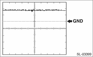
(1) Waveform 1
Item | Content |
Measured terminal | (B574) No. 1 (VC5) ←> (B574) No. 24 (AGND) |
Equipment setting | 2 V/DIV, 200 ms/DIV |
Measuring condition | Within 30 seconds after the push button ignition switch is pressed with IG OFF and access key not in the passenger room |
(2) Waveform 2
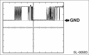
Item | Content |
Measured terminal | (B574) No. 7 (CODE) ←> (B574) No. 24 (AGND) |
Equipment setting | 2 V/DIV, 20 ms/DIV |
Measuring condition | Turn the ignition switch to OFF and with the access key near the push button ignition switch, press the push button ignition switch. *1 |
NOTE:
*1: Remove the access key battery before checking.
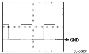
(3) Waveform 3
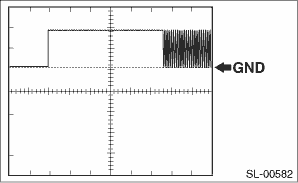
Item | Content |
Measured terminal | (B574) No. 9 (TXCT) ←> (B574) No. 24 (AGND) |
Equipment setting | 2 V/DIV, 20 ms/DIV |
Measuring condition | Within 30 seconds after the push button ignition switch is pressed with IG OFF and access key not in the passenger room |
(4) Waveform 4
Item | Content |
Measured terminal | (B572) No. 13 (EGIO) ←> (B572) No. 11 (GND) |
Equipment setting | 5 V/DIV, 100 ms/DIV |
Measuring condition | Within 3 seconds after engine has been initially ignited or within 3 seconds after initial IG ON following battery removal and installation |
(5) Waveform 5
Item | Content |
Equipment setting | 5 V/DIV, 100 ms/DIV |
2. ID CODE BOX
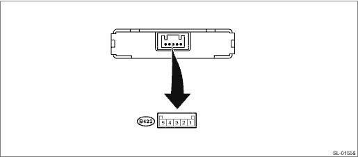
Terminal No. | Terminal symbol | Contents |
 Wiring diagram
KEYLESS ACCESS WITH PUSH BUTTON START SYSTEM (DIAGNOSTICS) > Control Module I/O SignalWIRING DIAGRAM• Refer to “Keyless Access System” in the wiring diagram. Keyless Access Syste ...

Other materials:
Removal
EXTERIOR BODY PANELS > Front HoodREMOVAL1. FRONT HOOD PANELCAUTION:The hood COMPL - front is heavy. When removing or installing the hinge COMPL - front hood, be sure to work in a group of two or more.1. Open the hood COMPL - front.2. Remove the clips, and remove the insulator - front hood.3. Remo ...
Preparation tool
LUBRICATION(H4DO) > General DescriptionPREPARATION TOOL1. SPECIAL TOOLILLUSTRATIONTOOL NUMBERDESCRIPTIONREMARKS18332AA000OIL FILTER WRENCHUsed for removing and installing oil filter (black). (Outer diameter: 68 mm (2.68 in)) — SUBARU SELECT MONITOR 4Used for setting of each function and trouble ...
Note
LIGHTING SYSTEM > Turn Signal Light and Hazard Light SystemNOTEFor operation procedures of each component of the turn signal and hazard light system, refer to the respective sections.• Combination switch (light): Combination Switch (Light)">• Front turn signal light bulb: Fr ...
