Subaru Crosstrek Service Manual: Electrical specification
HVAC SYSTEM (AUTO A/C) (DIAGNOSTICS) > Auto A/C Control Module I/O Signal
ELECTRICAL SPECIFICATION
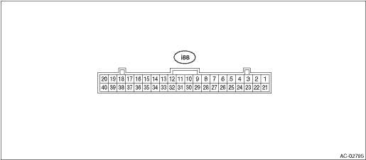
Terminal No. | Content | Measuring condition | Standard | |
1 | Mode door actuator #4 | Digital signal; can not be measured | — | |
2 | Mode door actuator #3 | Digital signal; can not be measured | — | |
3 | Mode door actuator #2 | Digital signal; can not be measured | — | |
4 | Mode door actuator #1 | Digital signal; can not be measured | — | |
6 | Intake door actuator (FRESH) | FRESH mode | 8 V or more | |
8 | Intake door actuator (RECIRC) | RECIRC mode | 8 V or more | |
9 | Blower fan ON signal | Blower fan is ON | 1 V or less | |
10 | Intake door potentiometer power supply | Ignition switch ON | 5 V | |
11 | A/C cut-off signal | A/C is cut off | 1 V or less | |
12 | Intake door potentiometer signal | Ignition switch ON | 0 — 5 V | |
14 | GND for sensors | Always | 1 V or less | |
15 | ACC power supply | ACC ON | Battery voltage | |
16 | Sunload sensor | Sunlight is contacting sensor | 1 — 4 V | |
17 | RECIRC sensor | Ignition switch ON | 25°C: 2.5 V | |
18 | Post evaporator sensor | Depends on temperature after the evaporator. | 1 — 4.5 V | |
19 | CAN Lo | Digital signal; can not be measured | — | |
20 | CAN Hi | Digital signal; can not be measured | — | |
21 | Air mix door actuator LH #4*2 | Digital signal; can not be measured | — | |
22 | Air mix door actuator LH #3*2 | Digital signal; can not be measured | — | |
23 | Air mix door actuator LH #2*2 | Digital signal; can not be measured | — | |
24 | Air mix door actuator LH #1*2 | Digital signal; can not be measured | — | |
25 | Air mix door actuator #4 *1 or air mix door actuator RH #4 *2 | Digital signal; can not be measured | — | |
26 | Air mix door actuator #3 *1 or air mix door actuator RH #3 *2 | Digital signal; can not be measured | — | |
27 | Air mix door actuator #2 *1 or air mix door actuator RH #2 *2 | Digital signal; can not be measured | — | |
28 | Air mix door actuator #1 *1 or air mix door actuator RH #1f *2 | Digital signal; can not be measured | — | |
31 | BATT | Always | Battery voltage | |
32 | IGN | Ignition ON | Battery voltage | |
34 | GND | Always | 1 V or less | |
35 | ILL− | Illumination ON (measure between 37 — 35) | Battery voltage | |
37 | ILL+ | |||
40 | Fan control signal | Ignition switch: ON, Blower switch: ON | 1st | Approx. 9 V |
2nd | Approx. 8 V | |||
3rd | Approx. 7 V | |||
4th | Approx. 6 V | |||
5th | Approx. 5 V | |||
6th | Approx. 3.5 V | |||
7th | Approx. 0.5 V | |||
*1: Without left/right independent air conditioning function
*2: With left/right independent air conditioning function

 Wiring diagram
HVAC SYSTEM (AUTO A/C) (DIAGNOSTICS) > Auto A/C Control Module I/O SignalWIRING DIAGRAM1. AIR CONDITIONER AUTO A/C MODELRefer to “Air Conditioning System” in the wiring diagram. Air Co ...
Other materials:
Driving on snowy and icy roads
When operating the Subaru Ascent on snow-covered or icy roads, it is essential
to adopt smooth and controlled driving techniques. Sudden braking, rapid acceleration,
high speeds, or sharp steering inputs can easily lead to skidding or loss of traction,
especially in low-grip conditions.
Alway ...
Note
EyeSight > Switches and HarnessNOTE1. PRE-COLLISION BRAKE OFF SWITCH & LANE DEPARTURE WARNING OFF SWITCHThe pre-collision brake OFF & lane departure warning OFF switch is integrated in the stereo camera cover assembly.If the pre-collision brake OFF & lane departure warning OFF switch ...
Operation
ENTERTAINMENT > Telematics SystemOPERATION1. REGISTRATION (COMM CHECK)CAUTION:Because it will go back to Factory mode when the signal is weak, that you do not press the i button more than 2 seconds during a communication check. If it had returned to Factory mode, carrying out the CommCheck again. ...
