Subaru Crosstrek Service Manual: Electrical specification
EyeSight (DIAGNOSTICS) > Control Module I/O Signal
ELECTRICAL SPECIFICATION
1. STEREO CAMERA
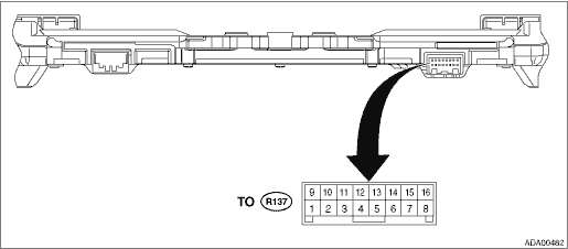
Terminal No. | Content | Measuring condition | Standard |
(R137) No. 1 | — | — | — |
(R137) No. 2 | — | — | — |
(R137) No. 3 | — | — | — |
(R137) No. 4 | — | — | — |
(R137) No. 5 | — | — | — |
(R137) No. 6 ←> Chassis ground | Ignition power supply | Ignition switch OFF > ON | Less than 1 V > 9 — 16 V |
(R137) No. 7 ←> Chassis ground | GND | Always | Less than 1 ? |
(R137) No. 8 ←> Chassis ground | Battery power supply | Always | 9 — 16 V |
(R137) No. 9 ←> Chassis ground | CAN L | Always | 1 k? or more |
(R137) No. 10 ←> Chassis ground | CAN H | Always | 1 k? or more |
(R137) No. 11 | — | — | — |
(R137) No. 12 ←> Chassis ground | Pre-collision brake OFF switch input | Pre-collision brake OFF switch OFF > ON | Approx. 1 k? > less than 1 ? |
(R137) No. 13 ←> Chassis ground | Lane departure warning OFF switch input | Lane departure warning OFF switch OFF > ON | Approx. 1 k? > less than 1 ? |
(R137) No. 14 ←> (R137) No. 15 | EyeSight steering switch input | ALL OFF (no switch operation) | 3.6 V — 4.5 V |
ALL OFF > RES/+ ON | 2.6 V — 3.5 V | ||
ALL OFF > following distance ON | 3.6 V — 4.5 V | ||
ALL OFF > SET/− ON | 0.6 V — 1.5 V | ||
ALL OFF > CRUISE ON | 0.0 V — 0.5 V | ||
(R137) No. 15 ←> Chassis ground | EyeSight steering switch GND | Always | Less than 1 ? |
(R137) No. 16 ←> (R137) No. 15 | EyeSight steering switch input | ALL OFF (no switch operation) | 2.6 V — 5.0 V |
ALL OFF > RES/+ ON | 2.6 V — 5.0 V | ||
ALL OFF > following distance ON | 0.0 V — 2.5 V | ||
ALL OFF > SET/− ON | 2.6 V — 5.0 V | ||
ALL OFF > CRUISE ON | 2.6 V — 5.0 V |
2. ENGINE CONTROL MODULE (ECM)
For details on the input/output signals for the engine control module, refer to ENGINE (DIAGNOSTICS). Engine Control Module (ECM) I/O Signal">
3. VDC CONTROL MODULE (VDCCM)
For details on the input/output signals for VDC control module, refer to VDC (DIAGNOSTICS). Control Module I/O Signal > ELECTRICAL SPECIFICATION">
4. TRANSMISSION CONTROL MODULE (TCM)
For details on the input/output signals for the transmission control module, refer to AUTOMATIC TRANSMISSION (DIAGNOSTICS). Transmission Control Module (TCM) I/O Signal">
5. BODY INTEGRATED UNIT
Refer to the BODY CONTROL SYSTEM (DIAGNOSTICS) for the I/O Signal of the body integrated unit. Control Module I/O Signal > ELECTRICAL SPECIFICATION">
6. COMBINATION METER
For details on the input/output signals for the combination meter, refer to INSTRUMENTATION/DRIVER INFO (DIAGNOSTICS). Control Module I/O Signal > ELECTRICAL SPECIFICATION">
7. MFD
For details on the input/output signals for MFD, refer to INSTRUMENTATION/DRIVER INFO (DIAGNOSTICS). Control Module I/O Signal > ELECTRICAL SPECIFICATION">

 System block diagram
EyeSight (DIAGNOSTICS) > Control Module I/O SignalSYSTEM BLOCK DIAGRAMMain signals used between stereo camera and relevant CM*: With high grade MFD only ...
Other materials:
Removal
EXTERIOR BODY PANELS > Door Sash TapeREMOVAL1. FRONT DOOR1. Disconnect the ground cable from battery and wait for at least 60 seconds before starting work. NOTE">2. Remove the trim panel - front door. Door Trim > REMOVAL">3. Remove the outer mirror assembly. Outer Mirror Ass ...
Inspection
CONTROL SYSTEMS > AT Shift Lock Control SystemINSPECTION1. SHIFT LOCK OPERATION• Model without push button ignition switchSTEPCHECKYESNO1.CHECK COMMUNICATION OF SUBARU SELECT MONITOR.1) Turn the ignition switch to ON.2) Using the Subaru Select Monitor, check whether communication to all sys ...
Front seats
WARNING
Never adjust the seat while driving
to avoid loss of vehicle control
and personal injury.
Before adjusting the seat, make
sure the hands and feet of rear
seat passengers and cargo are
clear of the adjusting mechanism.
After adjusting the seat, push it
slightly to make sur ...
