Subaru Crosstrek Service Manual: Dtc p1449 evap system clog detected (air filter)
ENGINE (DIAGNOSTICS)(H4DO) > Diagnostic Procedure with Diagnostic Trouble Code (DTC)
DTC P1449 EVAP SYSTEM CLOG DETECTED (AIR FILTER)
DTC DETECTING CONDITION:
Detected when two consecutive driving cycles with fault occur.
CAUTION:
After servicing or replacing faulty parts, perform Clear Memory Mode Clear Memory Mode > OPERATION"> , and Inspection Mode Inspection Mode > PROCEDURE">.
| STEP | CHECK | YES | NO |
1.CHECK FOR ANY OTHER DTC ON DISPLAY.
Is any other DTC displayed?
Check the appropriate DTC using the “List of Diagnostic Trouble Code (DTC)”. List of Diagnostic Trouble Code (DTC)">
Diagnostic Procedure with Diagnostic Trouble Code (DTC) > DTC P1449 EVAP SYSTEM CLOG DETECTED (AIR FILTER)">Go to Step 2.
2.CHECK DRAIN TUBE B OF LEAK CHECK VALVE ASSEMBLY.
Is the drain tube B of leak check valve assembly clogged?
Replace the drain tube B of leak check valve assembly. Leak Check Valve Assembly">
Diagnostic Procedure with Diagnostic Trouble Code (DTC) > DTC P1449 EVAP SYSTEM CLOG DETECTED (AIR FILTER)">Go to Step 3.
3.CHECK DRAIN HOSE AND DRAIN TUBE C BETWEEN LEAK CHECK VALVE ASSEMBLY AND DRAIN SEPARATOR.
Is the drain hose or the drain tube C between leak check valve assembly and drain separator clogged?
Replace the drain hose or the drain tube C between leak check valve assembly and drain separator. Drain Separator">
Diagnostic Procedure with Diagnostic Trouble Code (DTC) > DTC P1449 EVAP SYSTEM CLOG DETECTED (AIR FILTER)">Go to Step 4.
4.CHECK DRAIN SEPARATOR.
Is the drain separator clogged?
Replace the drain separator. Drain Separator">
Diagnostic Procedure with Diagnostic Trouble Code (DTC) > DTC P1449 EVAP SYSTEM CLOG DETECTED (AIR FILTER)">Go to Step 5.
5.CHECK INTAKE HOSE AND CONNECTOR BETWEEN DRAIN SEPARATOR AND VEHICLE BODY.
Is the intake hose or the connector between drain separator and vehicle body clogged?
Replace the intake hose or the connector between drain separator and vehicle body. Drain Separator">
Replace the leak check valve assembly. Leak Check Valve Assembly">
1. OUTLINE OF DIAGNOSIS
Detect the drain filter clogging by the pressure change during purge introduction.
Judge as drain filter clogging malfunction if the pressure in the evaporative emission system piping suddenly decreases by the purging.
2. COMPONENT DESCRIPTION
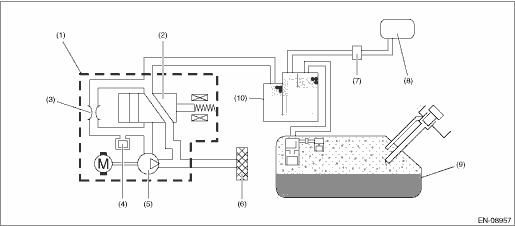
(1) | Leak check valve ASSY | (5) | Vacuum pump | (9) | Fuel tank |
(2) | Switching valve | (6) | Drain filter | (10) | Canister |
(3) | Reference orifice (0.02 inch orifice) | (7) | Purge control solenoid valve | ||
(4) | Pressure sensor | (8) | Intake manifold |
3. EXECUTION CONDITION
Secondary parameters | Execution condition |
Battery voltage | ≥ 10.9 V |
Elapsed time after ignition switch ON | ≥ 20000 ms |
Evaporative Leak Check Module vacuum pump | Not in operation |
Evaporative Leak Check Module switching valve | Open |
4. GENERAL DRIVING CYCLE
Perform the diagnosis continuously when purging is performed after 20000 ms have passed since the engine started.
5. DIAGNOSTIC METHOD

Calculate the difference between the Evaporative Leak Check Module pressure sensor output value of 5 seconds ago and the value at the present moment, and if the value is greater than the judgment value, detect as filter clogging trouble and judge as malfunction.
Judge as NG when the following conditions are established.
Malfunction Criteria | Threshold Value |
|Pressure sensor output value as of 5 seconds ago − Current pressure sensor output value| | > Value from Map |
Vehicle speed km/h (MPH) | 0 (0) | 20 (12.4) | 40 (24.9) | 60 (37.3) | 80 (49.7) | 100 (62.1) | 120 (74.6) | 300 (186.4) |
|Pressure sensor output value as of 5 seconds ago − Current pressure sensor output value| kPa (mmHg, inHg) | 1.4 (10.352 , 0.4) | 1.4 (10.352 , 0.4) | 1.4 (10.352 , 0.4) | 1.4 (10.352 , 0.4) | 1.4 (10.352 , 0.4) | 1.4 (10.352 , 0.4) | 1.4 (10.352 , 0.4) | 2.4 (18.287 , 0.7) |
Time needed for diagnosis: 1 seconds
Malfunction indicator light illumination: Illuminates when malfunction occurs in 2 continuous driving cycles.
 Dtc p1160 throttle return spring
ENGINE (DIAGNOSTICS)(H4DO) > Diagnostic Procedure with Diagnostic Trouble Code (DTC)DTC P1160 THROTTLE RETURN SPRINGNOTE:For the diagnostic procedure, refer to DTC P2101. Diagnostic Procedure with ...
 Dtc p1451 evap system clog detected (pipe)
ENGINE (DIAGNOSTICS)(H4DO) > Diagnostic Procedure with Diagnostic Trouble Code (DTC)DTC P1451 EVAP SYSTEM CLOG DETECTED (PIPE)DTC DETECTING CONDITION:Detected when two consecutive driving cycles wi ...
Other materials:
Removal
ENTERTAINMENT > Data Communication ModuleREMOVAL1. DATA COMMUNICATION MODULECAUTION:Before handling the airbag system components, always refer to “CAUTION” of “General Description” in “AIRBAG SYSTEM”.1. Disconnect the ground cable from battery and wait for at l ...
Inspection
BRAKE > Brake FluidINSPECTIONCAUTION:• Do not let brake fluid come into contact with the painted surface of the vehicle body. Wash away with water immediately and wipe off if it is spilled by accident.• Do not reuse drained brake fluid. When refilling brake fluid, always refill new br ...
Disassembly
EMISSION CONTROL (AUX. EMISSION CONTROL DEVICES)(H4DO) > Leak Check Valve AssemblyDISASSEMBLY1. Remove the drain separator from the leak check valve assembly. Drain Separator > REMOVAL">2. Disconnect the drain tube from the leak check valve assembly.NOTE:Disconnect the quick connector ...
