Subaru Crosstrek Service Manual: Dtc p081a starter disable circuit low
ENGINE (DIAGNOSTICS)(H4DO) > Diagnostic Procedure with Diagnostic Trouble Code (DTC)
DTC P081A STARTER DISABLE CIRCUIT LOW
DTC detecting condition:
Immediately at fault recognition
Trouble symptom:
Failure of engine to start
CAUTION:
After servicing or replacing faulty parts, perform Clear Memory Mode Clear Memory Mode > OPERATION"> , and Inspection Mode Inspection Mode > PROCEDURE">.
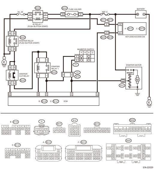
Wiring diagram:
Engine electrical system Engine Electrical System">
| STEP | CHECK | YES | NO |
1.CHECK HARNESS BETWEEN STARTER RELAY (PUSH BUTTON START) CONNECTOR AND STARTER CUT RELAY CONNECTOR.
1) Turn the ignition to OFF.
2) Remove the starter relay (push button start).
3) Remove the starter cut relay.
4) Measure the resistance of harness between starter relay (push button start) connector and starter cut relay connector.
Connector & terminal
(B225) No. 28 — (B225) No. 42:
Is the resistance less than 1 ??
Diagnostic Procedure with Diagnostic Trouble Code (DTC) > DTC P081A STARTER DISABLE CIRCUIT LOW">Go to Step 2.
Repair the open circuit in harness between starter relay (push button start) connector and starter cut relay connector.
2.CHECK HARNESS BETWEEN ECM AND STARTER CUT RELAY CONNECTOR.
1) Disconnect the connector from ECM.
2) Measure the resistance of harness between ECM connector and starter cut relay connector.
Connector & terminal
(B135) No. 34 — (B225) No. 40:
Is the resistance less than 1 ??
Diagnostic Procedure with Diagnostic Trouble Code (DTC) > DTC P081A STARTER DISABLE CIRCUIT LOW">Go to Step 3.
Repair the open circuit of harness between ECM connector and starter cut relay connector.
3.CHECK STARTER CUT RELAY.
1) Connect the battery to starter cut relay terminals No. 40 and No. 42.
2) Measure the resistance between starter cut relay terminals.
Terminals
No. 41 — No. 44:
Is the resistance 1 M? or more?
Repair the poor contact of ECM connector.
Replace the starter cut relay. Starter Cut Relay">
1. OUTLINE OF DIAGNOSIS
Detect abnormal continuity in the starter cut relay.
Judge as NG when the starter cut relay output line is open.
2. EXECUTION CONDITION
Secondary Parameters | Execution condition |
Battery voltage | ≥ 8 V |
Engine speed | Increase from 0 rpm to 500 rpm or more |
Vehicle speed | < 1 km/h (0.6 MPH) |
Starter cut relay command | OFF |
3. GENERAL DRIVING CYCLE
Perform the diagnosis only once after the enable conditions have been established.
4. DIAGNOSTIC METHOD
Judge as NG when the following conditions are established.
Malfunction Criteria | Threshold Value |
Starter cut relay control voltage that exceeds battery voltage ? 0.34 | Not detected |
Time Needed for Diagnosis: Less than 1 second
Malfunction Indicator Light Illumination: Illuminates as soon as a malfunction occurs.
 Dtc p0700 transmission control system (mil request)
ENGINE (DIAGNOSTICS)(H4DO) > Diagnostic Procedure with Diagnostic Trouble Code (DTC)DTC P0700 TRANSMISSION CONTROL SYSTEM (MIL REQUEST)NOTE:For the diagnostic procedure, refer to CVT section. Basi ...
 Dtc p1160 throttle return spring
ENGINE (DIAGNOSTICS)(H4DO) > Diagnostic Procedure with Diagnostic Trouble Code (DTC)DTC P1160 THROTTLE RETURN SPRINGNOTE:For the diagnostic procedure, refer to DTC P2101. Diagnostic Procedure with ...
Other materials:
Tire replacement
The tires and wheels of your Subaru Ascent are carefully selected to match the
vehicle’s design characteristics, ensuring optimal handling, comfort, and durability.
Replacing them with incorrect specifications can negatively impact performance and
safety.
Always use tires that match the ori ...
Locking and unlocking from the outside
NOTE
If you unlock the driver's door of your Subaru Ascent using a key (including
the emergency key) while the alarm system is armed, opening the door will trigger
the alarm, causing the vehicle horn to sound. To stop the alarm in the Subaru Ascent,
perform one of the following actions:
...
Removal
HVAC SYSTEM (HEATER, VENTILATOR AND A/C) > In-Vehicle Sensor (Auto A/C Model)REMOVALCAUTION:Be careful not to damage the sensors and interior trims when removing.1. Disconnect the battery ground cable and wait for at least 60 seconds before starting work. NOTE">2. Remove the cover assemb ...
