
Subaru Crosstrek Service Manual: Dtc p0685 ecm/pcm power relay control circuit/open
ENGINE (DIAGNOSTICS)(H4DO) > Diagnostic Procedure with Diagnostic Trouble Code (DTC)
DTC P0685 ECM/PCM POWER RELAY CONTROL CIRCUIT/OPEN
DTC DETECTING CONDITION:
Detected when two consecutive driving cycles with fault occur.
CAUTION:
After servicing or replacing faulty parts, perform Clear Memory Mode Clear Memory Mode > OPERATION"> , and Inspection Mode Inspection Mode > PROCEDURE">.
WIRING DIAGRAM:
Engine electrical system Engine Electrical System">
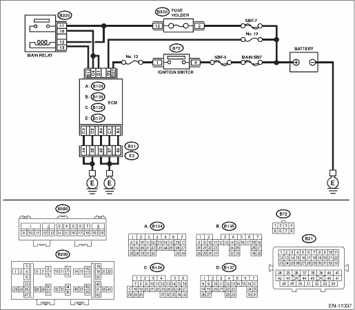
| STEP | CHECK | YES | NO |
1.CHECK ECM CONNECTOR.
Check the connecting condition of ECM connector.
Is the ECM connector correctly connected?
Diagnostic Procedure with Diagnostic Trouble Code (DTC) > DTC P0685 ECM/PCM POWER RELAY CONTROL CIRCUIT/OPEN">Go to Step 2.
Connect the ECM connector correctly.
2.CHECK HARNESS BETWEEN ECM AND MAIN RELAY CONNECTOR.
1) Turn the ignition switch to OFF.
2) Measure the voltage between ECM connector and engine ground.
Connector & terminal
(B136) No. 6 (+) — Engine ground (−):
(B137) No. 1 (+) — Engine ground (−):
Is the voltage 10 V or more?
Repair the harness and connector.
NOTE:
In this case, repair the following item:
• Short circuit to power supply in harness between ECM connector and main relay connector
• Defective main relay
Diagnostic Procedure with Diagnostic Trouble Code (DTC) > DTC P0685 ECM/PCM POWER RELAY CONTROL CIRCUIT/OPEN">Go to Step 3.
3.CHECK HARNESS BETWEEN ECM AND MAIN RELAY CONNECTOR.
1) Turn the ignition switch to OFF.
2) Remove the main relay.
3) Disconnect the connector from ECM.
4) Measure the resistance between the ECM connector and engine ground.
Connector & terminal
(B135) No. 13 — Engine ground:
Is the resistance 1 M? or more?
Repair the poor contact of ECM connector.
Repair the short circuit to ground in harness between ECM connector and main relay connector.
1. OUTLINE OF DIAGNOSIS
Detect the main relay stuck to ON.
Judge as NG when ECM keeps operating for more than predetermined time although the main relay does not turn to OFF after ignition switch is turned to OFF.
2. COMPONENT DESCRIPTION
The main relay controls the current in the coil section to switch ON/OFF the ECM by receiving instructions from the ignition switch and Evaporative Leak Check Module.
3. EXECUTION CONDITION
Secondary Parameters | Execution condition |
Main relay | OFF instruction |
4. GENERAL DRIVING CYCLE
Perform the diagnosis only once when the enable conditions are established with the ignition switch OFF > ON.
5. DIAGNOSTIC METHOD
If the duration of time while the following conditions are met is longer than the time indicated, judge as NG.
Malfunction Criteria | Threshold Value |
ECM status | In operation |
Time Needed for Diagnosis: 2500 ms
Malfunction Indicator Light Illumination: Illuminates when malfunction occurs in 2 continuous driving cycles.
 Dtc p062f internal control module eeprom error
ENGINE (DIAGNOSTICS)(H4DO) > Diagnostic Procedure with Diagnostic Trouble Code (DTC)DTC P062F INTERNAL CONTROL MODULE EEPROM ERRORNOTE:For the diagnostic procedure, refer to DTC P0606. Diagnostic ...
 Dtc p0700 transmission control system (mil request)
ENGINE (DIAGNOSTICS)(H4DO) > Diagnostic Procedure with Diagnostic Trouble Code (DTC)DTC P0700 TRANSMISSION CONTROL SYSTEM (MIL REQUEST)NOTE:For the diagnostic procedure, refer to CVT section. Basi ...
Other materials:
Dtc b1822 short in side airbag rh (to ground)
AIRBAG SYSTEM (DIAGNOSTICS) > Diagnostic Chart with Trouble CodeDTC B1822 SHORT IN SIDE AIRBAG RH (TO GROUND)Diagnosis start condition:Ignition voltage is 10 V to 16 V.DTC detecting condition:• Side airbag harness (RH) circuit is shorted to ground.• Side airbag module (RH) is faulty.& ...
Preparation tool
FRONT SUSPENSION > General DescriptionPREPARATION TOOL1. SPECIAL TOOLILLUSTRATIONTOOL NUMBERDESCRIPTIONREMARKS927680000INSTALLER & REMOVER SETUsed for replacing the bushing front - front arm of front arm assembly.20299AG000REMOVER• Used for replacing the bushing rear - front arm of fron ...
Adjustment
CONTROL SYSTEMS > Select CableADJUSTMENT1. Shift the select lever to “N” range.2. Lift up the vehicle.3. Remove the center exhaust pipe. Center Exhaust Pipe > REMOVAL">4. Remove the center exhaust cover.5. Loosen the adjusting nuts on both sides.(A)Adjusting nut A(B)Adjust ...
