Subaru Crosstrek Service Manual: Dtc p0616 starter relay "a" circuit low
ENGINE (DIAGNOSTICS)(H4DO) > Diagnostic Procedure with Diagnostic Trouble Code (DTC)
DTC P0616 STARTER RELAY "A" CIRCUIT LOW
DTC detecting condition:
Immediately at fault recognition
CAUTION:
After servicing or replacing faulty parts, perform Clear Memory Mode Clear Memory Mode > OPERATION"> , and Inspection Mode Inspection Mode > PROCEDURE">.
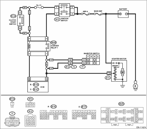
Wiring diagram:
Engine electrical system Engine Electrical System">
| STEP | CHECK | YES | NO |
1.CHECK FOR ANY OTHER DTC ON DISPLAY.
Is any other DTC displayed?
Check DTC using “List of Diagnostic Trouble Code (DTC)”. List of Diagnostic Trouble Code (DTC)">
Diagnostic Procedure with Diagnostic Trouble Code (DTC) > DTC P0616 STARTER RELAY "A" CIRCUIT LOW">Go to Step 2.
2.CHECK HARNESS BETWEEN ECM AND STARTER RELAY 1 CONNECTOR.
1) Turn the ignition switch to OFF.
2) Remove the starter relay 1.
3) Disconnect the connector from ECM.
4) Disconnect the connector from starter motor.
5) Measure the resistance of harness between ECM connector and starter relay 1 connector.
Connector & terminal
(B136) No. 16 — (B225) No. 1:
NOTE:
For CVT model, place the select lever in “P” range or “N” range.
Is the resistance less than 1 ??
Diagnostic Procedure with Diagnostic Trouble Code (DTC) > DTC P0616 STARTER RELAY "A" CIRCUIT LOW">Go to Step 3.
NOTE:
Check the following item and repair or replace if necessary.
• Open circuit of harness between ECM connector and starter relay 1 connector
• Poor contact of coupling connector
3.CHECK HARNESS BETWEEN ECM AND STARTER RELAY 1 CONNECTOR.
Measure the resistance between ECM connector and chassis ground.
Connector & terminal
(B137) No. 17 — Chassis ground:
Is the resistance 1 M? or more?
Repair the poor contact of ECM connector.
Repair the short circuit to ground in harness between ECM connector and starter relay 1 connector.
1. OUTLINE OF DIAGNOSIS
Detect abnormal continuity in the starter SW.
Judge as OFF NG when the starter SW signal remains OFF.
2. EXECUTION CONDITION
Secondary Parameters | Execution condition |
Battery voltage | ≥ 8 V |
Engine speed increases from 0 to more than 500 rpm | |
Vehicle speed | < 1 km/h |
Starter relay command | ON |
3. GENERAL DRIVING CYCLE
Always perform the diagnosis continuously.
4. DIAGNOSTIC METHOD
Judge as OFF NG when the following conditions are established.
Malfunction Criteria | Threshold Value |
The ECM did not detect the following. | |
Measured ECM input voltage which is supplied from 12 V battery system through the starter relay | ≥ 12 V battery system voltage ? 0.85 V |
Time Needed for Diagnosis: Less than 1 second
Malfunction Indicator Light Illumination: Illuminates as soon as a malfunction occurs.
 Dtc p060b internal control module a/d processing performance
ENGINE (DIAGNOSTICS)(H4DO) > Diagnostic Procedure with Diagnostic Trouble Code (DTC)DTC P060B INTERNAL CONTROL MODULE A/D PROCESSING PERFORMANCENOTE:For the diagnostic procedure, refer to DTC P0606 ...
 Dtc p0617 starter relay "a" circuit high
ENGINE (DIAGNOSTICS)(H4DO) > Diagnostic Procedure with Diagnostic Trouble Code (DTC)DTC P0617 STARTER RELAY "A" CIRCUIT HIGHDTC DETECTING CONDITION:Immediately at fault recognitionTROUBLE ...
Other materials:
Installation
SECURITY AND LOCKS > Keyless Access CMINSTALLATIONCAUTION:• When the control module related to immobilizer has been replaced, be sure to perform the registration of immobilizer system. For detailed operation procedure, refer to “Type D” described in “REGISTRATION MANUAL FO ...
Removal
SUNROOF/T-TOP/CONVERTIBLE TOP (SUNROOF) > Glass LidREMOVAL1. GLASS LID1. Completely close the lid assembly - sunroof, and open the sunshade assembly.2. Remove the TORX® bolt, and then remove the lid assembly - sunroof.CAUTION:Be careful not to damage the lid assembly - sunroof.PREPARATION TOOL:T ...
Automatic rear climate control operation
Rear climate control screen
Rear climate control auto mode icon
Rear climate control panel lock icon (if equipped)
Fan speed
Airflow mode
The Subaru Ascent provides convenient rear climate management through the central
display, allowing rear passengers to enjoy a comfortable envi ...
