Subaru Crosstrek Service Manual: Dtc p060b internal control module a/d processing performance
ENGINE (DIAGNOSTICS)(H4DO) > Diagnostic Procedure with Diagnostic Trouble Code (DTC)
DTC P060B INTERNAL CONTROL MODULE A/D PROCESSING PERFORMANCE
NOTE:
For the diagnostic procedure, refer to DTC P0606. Diagnostic Procedure with Diagnostic Trouble Code (DTC) > DTC P0606 CONTROL MODULE PROCESSOR">
1. OUTLINE OF DIAGNOSIS
Judge as NG when any one of the followings is established.
(1) If the input amplifier circuit of throttle position sensor 1 is abnormal (quadruple amplification problem).
(2) If the A/D converter operation is abnormal (ADC malfunction).
2. COMPONENT DESCRIPTION
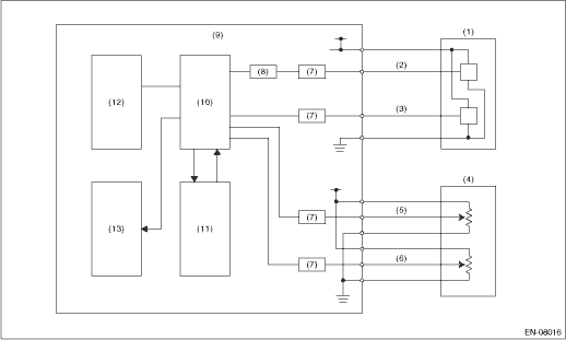
(1) | Throttle position sensor | (6) | Accelerator pedal position sensor 2 | (10) | CPU |
(2) | Throttle position sensor 1 | (7) | I/F circuit | (11) | Monitoring IC |
(3) | Throttle position sensor 2 | (8) | Amplifier circuit | (12) | EEPROM |
(4) | Accelerator pedal position sensor | (9) | Engine control module (ECM) | (13) | Output IC |
(5) | Accelerator pedal position sensor 1 |
3. EXECUTION CONDITION
Secondary Parameters | Execution condition |
Battery voltage | ≥ 6 V |
Target voltage | = 0 V |
Secondary Parameters | Execution condition |
Battery voltage | ≥ 6 V |
Target voltage | = 5 V |
4. GENERAL DRIVING CYCLE
Always perform the diagnosis continuously.
5. DIAGNOSTIC METHOD
Diagnosis 1
Judge as NG when the following conditions are established.
Malfunction Criteria | Threshold Value |
Actual voltage | > 0.01953125 V |
Time Needed for Diagnosis: 200 ms
Diagnosis 2
Judge as NG when the following conditions are established.
Malfunction Criteria | Threshold Value |
Actual voltage | > 4.979248047 V |
Time Needed for Diagnosis: 200 ms
Malfunction Indicator Light Illumination: Illuminates as soon as a malfunction occurs.
 Dtc p060a internal control module monitoring processor performance
ENGINE (DIAGNOSTICS)(H4DO) > Diagnostic Procedure with Diagnostic Trouble Code (DTC)DTC P060A INTERNAL CONTROL MODULE MONITORING PROCESSOR PERFORMANCENOTE:For the diagnostic procedure, refer to DTC ...
 Dtc p0616 starter relay "a" circuit low
ENGINE (DIAGNOSTICS)(H4DO) > Diagnostic Procedure with Diagnostic Trouble Code (DTC)DTC P0616 STARTER RELAY "A" CIRCUIT LOWDTC detecting condition:Immediately at fault recognitionCAUTION: ...
Other materials:
Total trailer weight
Total trailer weight
The total trailer weight (trailer weight plus
its cargo load) must never exceed the
maximum total trailer weight in the following
table.
Conditions
Maximum total trailer weight
When towing a trailer without brakes.
1,000 lbs (453 kg)
When ...
Removal
MANUAL TRANSMISSION AND DIFFERENTIAL(5MT) > Transmission CaseREMOVAL1. Remove the manual transmission assembly from the vehicle. Manual Transmission Assembly > REMOVAL">2. Remove the clutch release lever and the release bearing. Release Bearing and Lever > REMOVAL">3. Remo ...
Removal
CONTINUOUSLY VARIABLE TRANSMISSION(TR580) > Control Valve BodyREMOVALCAUTION:• Directly after the vehicle has been running or the engine has been idling for a long time, the CVTF is hot. Be careful not to burn yourself.• Be careful not to spill CVTF on the exhaust pipe to prevent it f ...
