Subaru Crosstrek Service Manual: Dtc p060a internal control module monitoring processor performance
ENGINE (DIAGNOSTICS)(H4DO) > Diagnostic Procedure with Diagnostic Trouble Code (DTC)
DTC P060A INTERNAL CONTROL MODULE MONITORING PROCESSOR PERFORMANCE
NOTE:
For the diagnostic procedure, refer to DTC P0606. Diagnostic Procedure with Diagnostic Trouble Code (DTC) > DTC P0606 CONTROL MODULE PROCESSOR">
1. OUTLINE OF DIAGNOSIS
Judge as NG when the monitoring IC operation is abnormal. (Monitoring IC malfunction)
2. COMPONENT DESCRIPTION
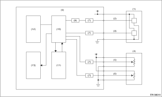
(1) | Throttle position sensor | (6) | Accelerator pedal position sensor 2 | (10) | CPU |
(2) | Throttle position sensor 1 | (7) | I/F circuit | (11) | Monitoring IC |
(3) | Throttle position sensor 2 | (8) | Amplifier circuit | (12) | EEPROM |
(4) | Accelerator pedal position sensor | (9) | Engine control module (ECM) | (13) | Output IC |
(5) | Accelerator pedal position sensor 1 |
3. EXECUTION CONDITION
Secondary Parameters | Execution condition |
(1) Battery voltage | ≥ 6 V |
(1) CPU intentionally sends a motor cut-off command to the observation IC | ON |
(2) Battery voltage | ≥ 6 V |
(2) CPU intentionally sends an incorrect data | ON |
(3) Battery voltage | ≥ 6 V |
4. GENERAL DRIVING CYCLE
Always perform the diagnosis continuously.
5. DIAGNOSTIC METHOD
Judge as OK and clear the NG when the malfunction criteria below are met.
Malfunction Criteria | Threshold Value |
(1) Throttle position Memory throttle position when monitoring | ≥ 2 ° |
(2) Motor cut-off signal from observation IC | = Not Detected |
(3) Written data in the observation IC register | ≠ Not Detected |
Time Needed for Diagnosis:
(1): 24 ms
(2): 24 ms
(3): 200 ms
Malfunction Indicator Light Illumination: Illuminates as soon as a malfunction occurs.
 Dtc p0606 control module processor
ENGINE (DIAGNOSTICS)(H4DO) > Diagnostic Procedure with Diagnostic Trouble Code (DTC)DTC P0606 CONTROL MODULE PROCESSORDTC detecting condition:Immediately at fault recognitionTrouble symptom:• ...
 Dtc p060b internal control module a/d processing performance
ENGINE (DIAGNOSTICS)(H4DO) > Diagnostic Procedure with Diagnostic Trouble Code (DTC)DTC P060B INTERNAL CONTROL MODULE A/D PROCESSING PERFORMANCENOTE:For the diagnostic procedure, refer to DTC P0606 ...
Other materials:
Front seats
WARNING
Never adjust the seat while driving
to avoid loss of vehicle control
and personal injury.
Before adjusting the seat, make
sure the hands and feet of rear
seat passengers and cargo are
clear of the adjusting mechanism.
After adjusting the seat, push it
slightly to make sur ...
Dtc p0345 camshaft position sensor "a" circuit bank 2
ENGINE (DIAGNOSTICS)(H4DO) > Diagnostic Procedure with Diagnostic Trouble Code (DTC)DTC P0345 CAMSHAFT POSITION SENSOR "A" CIRCUIT BANK 2DTC DETECTING CONDITION:Immediately at fault recognitionTROUBLE SYMPTOM:• Engine stall• Failure of engine to startCAUTION:After servicing ...
Tilt/telescopic steering wheel
WARNING
Do not adjust the steering wheel
tilt/telescopic position while driving.
This may cause loss of
vehicle control and result in
personal injury.
If the lever cannot be raised to
the fixed position, adjust the
steering wheel again. It is dangerous
to drive without locking
...
