Subaru Crosstrek Service Manual: Dtc p0606 control module processor
ENGINE (DIAGNOSTICS)(H4DO) > Diagnostic Procedure with Diagnostic Trouble Code (DTC)
DTC P0606 CONTROL MODULE PROCESSOR
DTC detecting condition:
Immediately at fault recognition
Trouble symptom:
• Improper idling
• Poor driving performance
CAUTION:
After servicing or replacing faulty parts, perform Clear Memory Mode Clear Memory Mode > OPERATION"> , and Inspection Mode Inspection Mode > PROCEDURE">.
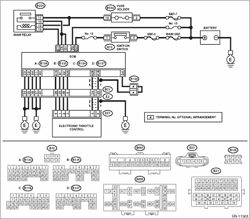
Wiring diagram:
Engine electrical system Engine Electrical System">
| STEP | CHECK | YES | NO |
1.CHECK INPUT VOLTAGE OF ECM.
1) Turn the ignition switch to ON.
2) Measure the voltage between ECM connector and chassis ground.
Connector & terminal
(B136) No. 6 (+) — Chassis ground (−):
(B137) No. 1 (+) — Chassis ground (−):
Is the voltage 10 — 13 V?
Diagnostic Procedure with Diagnostic Trouble Code (DTC) > DTC P0606 CONTROL MODULE PROCESSOR">Go to Step 2.
Repair the open or short to ground in the power supply circuit.
2.CHECK INPUT VOLTAGE OF ECM.
1) Start the engine.
2) Measure the voltage between ECM connector and chassis ground.
Connector & terminal
(B136) No. 6 (+) — Chassis ground (−):
(B137) No. 1 (+) — Chassis ground (−):
Is the voltage 13 — 15 V?
Diagnostic Procedure with Diagnostic Trouble Code (DTC) > DTC P0606 CONTROL MODULE PROCESSOR">Go to Step 3.
Repair the open or short to ground in the power supply circuit.
3.CHECK HARNESS BETWEEN ECM AND ELECTRONIC THROTTLE CONTROL CONNECTOR.
1) Turn the ignition switch to OFF.
2) Disconnect the connector from ECM.
3) Disconnect the connectors from electronic throttle control.
4) Measure the resistance of harness between ECM connector and electronic throttle control connector.
Connector & terminal
(B134) No. 19 — (E57) No. 5:
(B134) No. 29 — (E57) No. 3:
Is the resistance less than 1 ??
Diagnostic Procedure with Diagnostic Trouble Code (DTC) > DTC P0606 CONTROL MODULE PROCESSOR">Go to Step 4.
Repair the harness and connector.
NOTE:
In this case, repair the following item:
• Open circuit in harness between ECM connector and electronic throttle control connector
• Poor contact of coupling connector
4.CHECK ECM GROUND HARNESS.
1) Connect all connectors.
2) Turn the ignition to ON.
3) Measure the voltage between ECM connector and chassis ground.
Connector & terminal
(B134) No. 3 (+) — Chassis ground (−):
(B134) No. 4 (+) — Chassis ground (−):
(B136) No. 1 (+) — Chassis ground (−):
(B136) No. 2 (+) — Chassis ground (−):
(B136) No. 3 (+) — Chassis ground (−):
Is the voltage less than 1 V?
Check the connector for poor contact and check the harness.
Replace the ECM if no fault is found. Engine Control Module (ECM)">
Repair the harness and connector.
NOTE:
In this case, repair the following item:
• Open circuit in ground circuit
• Further tightening of the engine ground terminal
• Poor contact of coupling connector
1. OUTLINE OF DIAGNOSIS
Judge as NG when any one of the followings is established.
(1) If the CPU operation is abnormal (instruction/flow check).
(2) If the output IC operation is abnormal (output driver malfunction).
2. COMPONENT DESCRIPTION
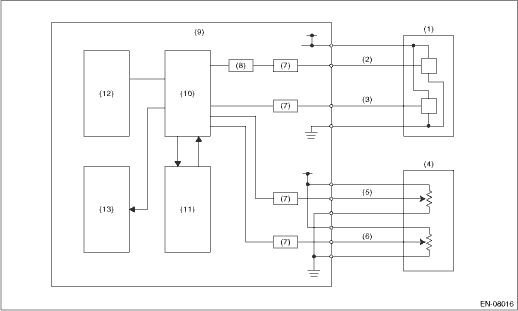
(1) | Throttle position sensor | (6) | Accelerator pedal position sensor 2 | (10) | CPU |
(2) | Throttle position sensor 1 | (7) | I/F circuit | (11) | Monitoring IC |
(3) | Throttle position sensor 2 | (8) | Amplifier circuit | (12) | EEPROM |
(4) | Accelerator pedal position sensor | (9) | Engine control module (ECM) | (13) | Output IC |
(5) | Accelerator pedal position sensor 1 |
3. EXECUTION CONDITION
Secondary Parameters | Execution condition |
(1) Ignition switch | ON |
(1) ETC control | Permission |
(2) Ignition switch | ON |
(2) Battery voltage | ≥ 10.9 V |
4. GENERAL DRIVING CYCLE
Always perform the diagnosis continuously.
5. DIAGNOSTIC METHOD
Judge as OK and clear the NG if any of the followings is established.
Malfunction Criteria | Threshold Value |
(1) Main CPU calculation result | The result and expected value match |
(2) Communication between output ICs | Possible to communicate |
(3) Step of calculation | Expected step of calculation |
(4)-1 Motor relay cut-off signal from observation IC | ON |
(4)-2 As defined by | |
Instruction error | Detect |
or | |
Instruction error | Detect |
(5) Driver IC bus signal | Did not change |
(6) Written data in the CAN register | ≠ Read data |
Time Needed for Diagnosis:
(1): 2 time(s)
(2): 512 ms
(3): 504 ms
(4): 48 ms
(5): 2500 ms
(6): Less than 1 second
Malfunction Indicator Light Illumination: Illuminates as soon as a malfunction occurs.
 Dtc p0605 internal control module read only memory (rom) error
ENGINE (DIAGNOSTICS)(H4DO) > Diagnostic Procedure with Diagnostic Trouble Code (DTC)DTC P0605 INTERNAL CONTROL MODULE READ ONLY MEMORY (ROM) ERRORNOTE:For the diagnostic procedure, refer to DTC P06 ...
 Dtc p060a internal control module monitoring processor performance
ENGINE (DIAGNOSTICS)(H4DO) > Diagnostic Procedure with Diagnostic Trouble Code (DTC)DTC P060A INTERNAL CONTROL MODULE MONITORING PROCESSOR PERFORMANCENOTE:For the diagnostic procedure, refer to DTC ...
Other materials:
Preparation for maintenance settings
1. Turn the ignition switch to the "ON"
position.
2. Push and hold the
button to show
the selection screen.
3. After the selection screen is displayed,
operate the "
" or "
" switch to show the
"Maintenance" item. Then, push the
button. ...
Clear memory mode Operation
AUTO HEADLIGHT BEAM LEVELER SYSTEM (DIAGNOSTICS) > Clear Memory ModeOPERATION1. On «Start» display, select «Diagnosis».2. On «Vehicle selection» display, input the target vehicle information and select «Confirmed».3. On «Main Menu» display, select «Each System».4. On «Select System» ...
Interior
Passenger compartment area
Second-row captain seat models
The Subaru Ascent interior is thoughtfully designed to maximize passenger comfort
and flexibility. In models equipped with second-row captain seats, occupants benefit
from enhanced accessibility and individual seating comfort, makin ...
