Subaru Crosstrek Service Manual: Dtc p0617 starter relay "a" circuit high
ENGINE (DIAGNOSTICS)(H4DO) > Diagnostic Procedure with Diagnostic Trouble Code (DTC)
DTC P0617 STARTER RELAY "A" CIRCUIT HIGH
DTC DETECTING CONDITION:
Immediately at fault recognition
TROUBLE SYMPTOM:
Failure of engine to start
CAUTION:
After servicing or replacing faulty parts, perform Clear Memory Mode Clear Memory Mode > OPERATION"> , and Inspection Mode Inspection Mode > PROCEDURE">.
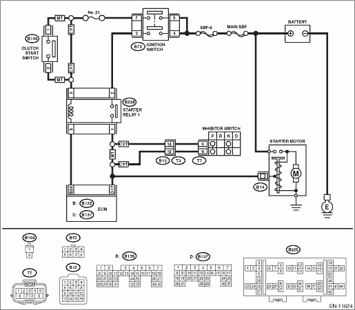
WIRING DIAGRAM:
Engine electrical system Engine Electrical System">
| STEP | CHECK | YES | NO |
1.CHECK FOR ANY OTHER DTC ON DISPLAY.
Is any other DTC displayed?
Check the appropriate DTC using the “List of Diagnostic Trouble Code (DTC)”. List of Diagnostic Trouble Code (DTC)">
Diagnostic Procedure with Diagnostic Trouble Code (DTC) > DTC P0617 STARTER RELAY "A" CIRCUIT HIGH">Go to Step 2.
2.CHECK HARNESS BETWEEN ECM AND STARTER RELAY 1 CONNECTOR.
1) Turn the ignition switch to OFF.
2) Disconnect the connector from ECM.
3) Turn the ignition switch to ON.
4) Measure the voltage between ECM connector and chassis ground.
Connector & terminal
(B136) No. 16 (+) — Chassis ground (−):
NOTE:
For CVT model, place the select lever in “P” range or “N” range.
Is the voltage 10 V or more?
Repair the short circuit to power in harness between ECM connector and starter relay 1 connector.
Repair the poor contact of ECM connector.
1. OUTLINE OF DIAGNOSIS
Detect abnormal continuity in the starter SW.
Judge as ON NG when the starter SW signal remains ON.
2. EXECUTION CONDITION
Secondary parameters | Execution condition |
Battery voltage | ≥ 8 V |
Engine speed | ≥ 500 rpm |
Starter relay command | OFF |
3. GENERAL DRIVING CYCLE
Always perform the diagnosis continuously.
4. DIAGNOSTIC METHOD
If the duration of time while the following conditions are met is longer than the time indicated, judge as NG.
Malfunction Criteria | Threshold Value |
Measured ECM input voltage which is supplied from 12 V battery system through the starter relay | ≥ 12 V battery system voltage ? 0.85 V |
Time Needed for Diagnosis: 30000 ms
Malfunction Indicator Light Illumination: Illuminates as soon as a malfunction occurs.
 Dtc p0616 starter relay "a" circuit low
ENGINE (DIAGNOSTICS)(H4DO) > Diagnostic Procedure with Diagnostic Trouble Code (DTC)DTC P0616 STARTER RELAY "A" CIRCUIT LOWDTC detecting condition:Immediately at fault recognitionCAUTION: ...
 Dtc p062f internal control module eeprom error
ENGINE (DIAGNOSTICS)(H4DO) > Diagnostic Procedure with Diagnostic Trouble Code (DTC)DTC P062F INTERNAL CONTROL MODULE EEPROM ERRORNOTE:For the diagnostic procedure, refer to DTC P0606. Diagnostic ...
Other materials:
Where to place a child restraint system
The following are SUBARU's recommendations
on where to place a child restraint
system in your vehicle.
A: Front passenger's seat
You should not install a child restraint
system (including a booster seat) due to
the hazard to children posed by the
passenger's airbag.
B: Rear seat, window- ...
Low tire pressure warning light (U.S.-spec. models)
When
the ignition switch is turned to the
"ON" position, the low tire pressure warning
light will illuminate for approximately 2
seconds to check that the tire pressure
monitoring system (TPMS) is functioning
properly. If there is no problem and all tires
are properly inflated, the light w ...
Installation
DRIVE SHAFT SYSTEM > Rear Drive ShaftINSTALLATION1. Replace the rear differential side oil seal. Rear Differential Side Oil Seal > REPLACEMENT">NOTE:After pulling out the drive shaft assembly, be sure to replace with a new oil seal.2. Insert the drive shaft assembly into the rear hub ...
